Magnetic head and method of manufacturing same, head suspension assembly and magnetic disk apparatus

a technology of magnetic head and suspension assembly, which is applied in the field of magnetic head, a method of manufacturing the magnetic head, a head suspension assembly and a magnetic disk apparatus, can solve the problems of low resistance of the whole magneto-resistive device, few opportunities for oxygen to bind, and relatively large variation of the resistance of the magneto-resistive device to achieve the effect of high stability of characteristics

Active Publication Date: 2007-07-19
TDK CORPARATION
View PDF14 Cites 2 Cited by
  • Summary
  • Abstract
  • Description
  • Claims
  • Application Information

AI Technical Summary

Benefits of technology

[0010] It is an object of the present invention to provide a magnetic head which comprises a magneto-resistive device having a magneto-resistive layer including an oxide layer but has less variations in the resistance of the magneto-resistive device before and after the magnetic head is left in a high temperature environment to have higher stability of the characteristics of the magnetic head against a high temperature environment, a method of manufacturing such a magnetic head, and a head suspension assembly and a magnetic disk apparatus which use the magnetic head.
[0011] The result of an additional investigation made by the present inventors has revealed that in a magnetic head comprising a magneto-resistive device having a magneto-resistive layer including an oxide layer and, for example, using a silicon film for an underlying layer of a protection film formed on ABS, the resistance of the magneto-resistive device relatively largely varies before and after the magnetic head is left in a high temperature environment for the following reason. It can be thought that when the magnetic head is left in a high temperature environment, oxygen present in the oxide film forming a part of the magneto-resistive device migrates into the underlying layer, so that the oxide layer contains less oxygen and thereby has a lower resistance. As a result, it can be thought that as a result, the resistance of the whole magneto-resistive device becomes lower, probably causing the resistance of the magneto-resistive device to relatively largely vary.
[0012] Consequently, the present inventors thought that when the underlying layer of the protection film was made of a material except for an oxide, if a layer made of an oxide of a metal or an oxide of a semiconductor was interposed between the underlying layer of the protection film and the oxide layer forming a part of the magneto-resistive layer so as to be in contact with the oxide layer forming the part of the magneto-resistive layer, oxygen present in the oxide layer forming the part of the magneto-resistive layer is less prone to go out of the oxide layer and remains within the oxide layer, even if the magnetic head was left in a high temperature environment. This is because the oxide of the metal or the oxide of the semiconductor has already bound with oxygen and therefore there is few opportunities for the oxygen to bind. The inventors further thought that from the fact that the oxygen present in the oxide layer forming the part of the magneto-resistive layer remains within the oxide layer even if the magnetic head is left in a high temperature environment, the resistance of the oxide layer would not be significantly reduced to cause less variations in the resistance of the magneto-resistive device. The inventors confirmed this hypothesis by an experiment.

Problems solved by technology

As a result, it can be thought that as a result, the resistance of the whole magneto-resistive device becomes lower, probably causing the resistance of the magneto-resistive device to relatively largely vary.
This is because the oxide of the metal or the oxide of the semiconductor has already bound with oxygen and therefore there is few opportunities for the oxygen to bind.

Method used


Image

  • Magnetic head and method of manufacturing same, head suspension assembly and magnetic disk apparatus
  • Magnetic head and method of manufacturing same, head suspension assembly and magnetic disk apparatus
  • Magnetic head and method of manufacturing same, head suspension assembly and magnetic disk apparatus

Examples


first embodiment

[0065] First, a magnetic head according to the present invention will be described with reference to FIGS. 1 to 5.

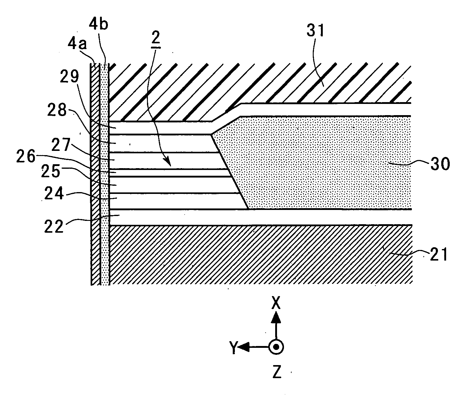
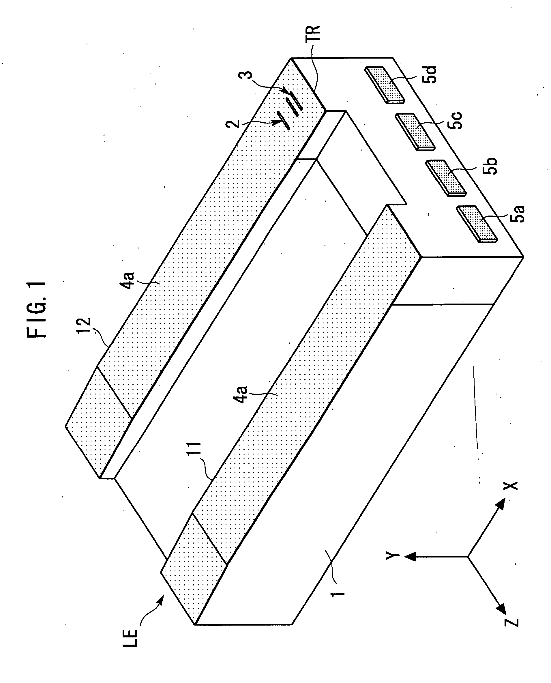
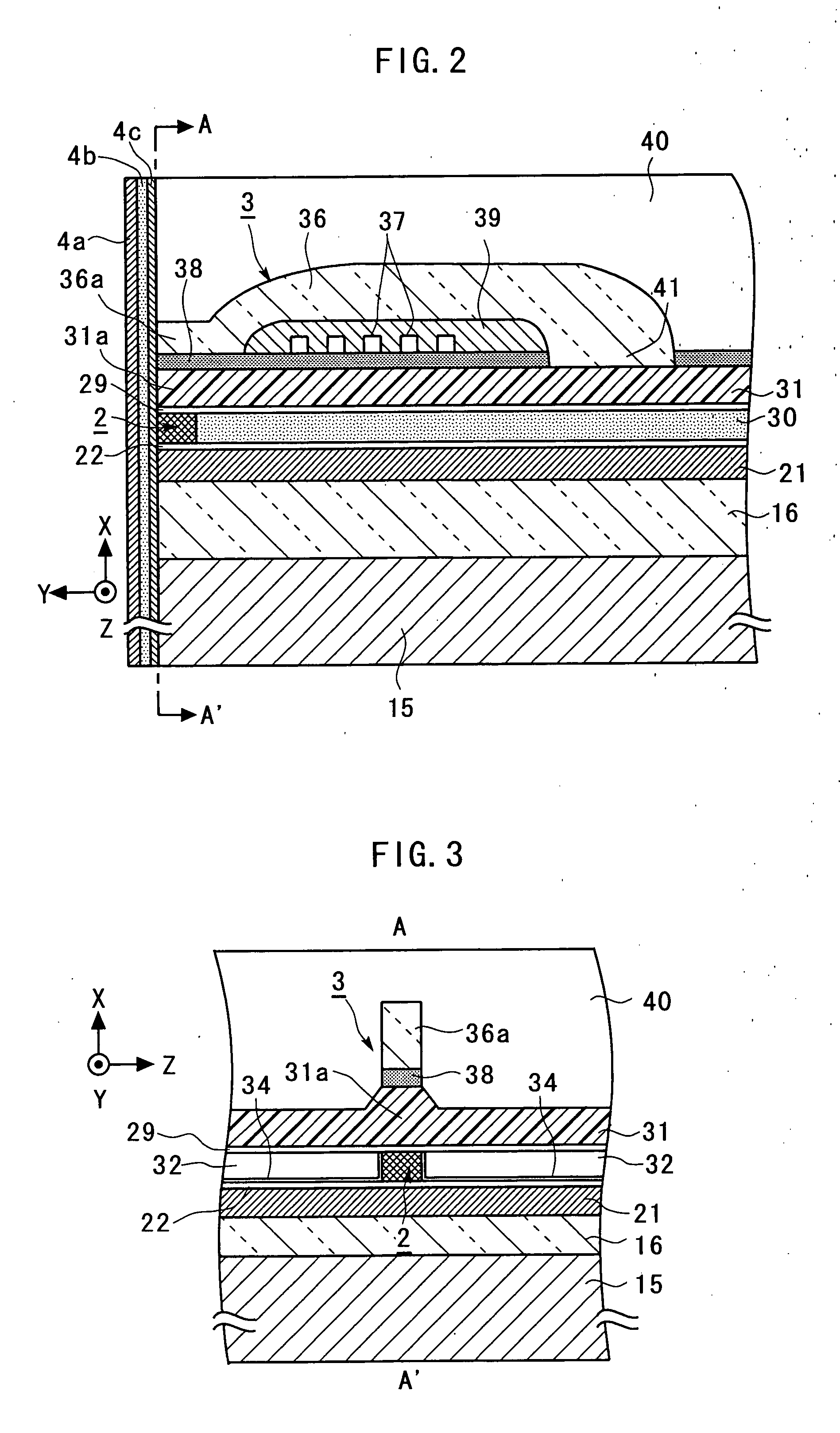
[0066]FIG. 1 is a general perspective view schematically illustrating the magnetic head according to the first embodiment of the present invention. FIG. 2 is an enlarged cross-sectional view schematically illustrating a portion of a TMR device 2 and an inductive magnetic transducing device 3 in the magnetic head illustrated in FIG. 1. FIG. 3 is a general sectional view taken along a line A-A′ indicated by arrows in FIG. 2. FIG. 4 is a further enlarged view illustrating around the TMR device 2 in FIG. 2. FIG. 5 is a further enlarged view around the TMR device 2 in FIG. 3. For facilitating the understanding, an X-axis, a Y-axis and a. Z-axis, orthogonal to one another, are defined as shown in FIG. 1 to 5 (the same applies to figures later described). The Z-axis direction indicated by the arrow is referred to as the “+Z-direction” or “+Z-side,” and the opposite direction is...

third embodiment

[0119] Subsequently, in the third embodiment, after the bar 102 is once left in the atmosphere, the bar 102 is etched for cleaning the surface and the like by dry etching such as sputter etching, ion beam etching or the like in the same vacuum chamber in which the variation reducing layer 4c is deposited.

[0120] Next, ion beam deposition or sputtering is performed using an oxide of a metal or a semiconductor (for example, Al, Si, Ti, V, Cr, Mn, Fe, Ni, Co, Cu, Zn, Zr, Nb, Mo, Hf, Ta, or W) as a target without using oxygen for a process gas to deposit the variation reducing layer 4c on the surface of the bar 102 on the ABS side.

[0121] Next, after the bar 102 is etched for cleaning the surface and the like by dry etching such as sputter etching, ion beam etching or the like in the same vacuum chamber in which the variation reducing layer 4c has been deposited, the underlying layer 4b made, for example, of Si is deposited on the variation reducing layer 4c by a sputtering method or the...

fourth embodiment

[0131] Next, a magnetic head according to the present invention will be described with reference to FIG. 16.

[0132]FIG. 16 is an enlarged cross-sectional view schematically illustrating a main portion of a magnetic head according to a fourth embodiment of the present invention, and corresponds to FIG. 4. In FIG. 16, components identical or corresponding to those in FIG. 4 are designated by the same reference numerals, and repetitive description thereon is omitted.

[0133] The magnetic head according to the fourth embodiment differs from the magnetic head according to the first embodiment only in the composition of the variation reducing layer 4c. In the first embodiment, the variation reducing layer 4c is made of the same material in any part thereof. In the fourth embodiment, on the other hand, respective portions 21a, 22a, 24a-29a, 31a of the variation reducing layer 4c which cover the layers 21, 22, 24-29, 31, respectively, are made of materials which are determined in accordance w...


PUM

PropertyMeasurementUnit
thicknessaaaaaaaaaa
pressureaaaaaaaaaa
accelerating currentaaaaaaaaaa

Abstract

A magnetic head has less variations in the resistance of a magneto-resistive device before and after the magnetic head is left in a high temperature environment so as to have higher stability of the characteristics of the magnetic head against a high temperature environment. A TMR device includes a tunnel barrier layer made of an oxide layer. A DLC film serving as a protection film and an underlying layer therefor are formed on an end face of the TMR device on an air bearing surface side. A layer made of an oxide of a metal or an oxide of a semiconductor is formed between the underlying layer and the end face of the tunnel barrier layer on the air bearing surface side to be in contact with the end face of the tunnel barrier layer.

Description

[0001] This is a Division of application Ser. No. 10 / 944,786 filed Sep. 21, 2004. The disclosure of the prior application is hereby incorporated by reference herein in its entirety.BACKGROUND OF THE INVENTION [0002] The present invention relates to a magnetic head, a method of manufacturing the magnetic head, a head suspension assembly and a magnetic disk apparatus. [0003] With the trend to a larger capacity and a smaller size of hard disk drives (HDD), heads are required to have a higher sensitivity and a larger output. To meet these requirements, strenuous efforts have been made to improve the characteristics of GMR heads (Giant Magneto-Resistive Head) currently available on the market. On the other hand, intense development is under way for a tunnel magneto-resistive head (TMR head) which can be expected to have a resistance changing ratio twice or more higher than the GMR head. [0004] Generally, the GMR head differs from the TMR head in the head structure due to a difference in ...

Claims


Application Information

Patent Timeline
Patent Type & Authority Applications(United States)
IPC IPC(8): G11B5/127G11B5/33G11B5/39
CPCB82Y10/00B82Y25/00G11B5/3906Y10T29/49032Y10T29/49043Y10T29/49041G11B5/3909
Inventor KAGAMI, TAKEOKUWASHIMA, TETSUYANAGAI, KENTARO
Owner TDK CORPARATION
Why Eureka
Try Eureka