Method and system for constructing pre-fabricated building

a prefabricated and building technology, applied in the field of building construction, can solve the problems of insufficient connection between prefabricated panels, inefficient hvac systems, and major construction costs and quality of manufacture, and achieve the effects of reducing labor costs, reducing the restriction of air circulation caused by air return ducts, and reducing the temperature in the hom

Inactive Publication Date: 2007-07-19
SUNSET MARKETING
View PDF16 Cites 42 Cited by
  • Summary
  • Abstract
  • Description
  • Claims
  • Application Information

AI Technical Summary

Benefits of technology

[0018] In the present invention, the accepted design of building walls with stud type framework is retained. However, the method of construction is changed as tasks performed on-site are instead completed in an off-site factory. A majority of currently common tasks, such as installing doors and windows, installing rough wiring, rough plumbing, placement of AC ducts, and applying wall facings, are done under strict quality control in the factory. For example, to build a four foot wall by traditional on site methods requires a carpenter, a block layer, an electrician, a plumber, HVAC tradesman, a dry wall crew and a painter. Time requirements are estimated in excess of one and one half hours to complete the work per four foot section. In contrast, the same four foot wall section can be constructed using the system and method of the present in approximately one minute. This rapid construction can be accomplished with a factory crew of ten workers. Further, it is estimated that labor costs are reduced to less than about 5% of traditional methods. This is accomplished by the factory placement of insulation, portions of rough wiring, and wall facings thereby eliminating the need for on site installation.
[0019] A typical full size wall segment of the present invention is 8 feet tall and 4 feet wide. Other panel widths of one foot, two feet, and three feet, headers, panels with pre-installed windows or doors, panels with one end framed to math roof slope and panels for special wall heights or widths are also contemplated by the present invention.
[0020] In accordance with the present invention, an interior space is defined by wall segments, ceiling panels and roof panels having steel and cement-faced surfaces. The space defined between the ceiling and roof panels (i.e., “attic space”) is used as a ductless cold air return. Each room of a building is connected to the attic space, for example, by a standard 6″×10″ register well known in the art. Thus, restrictions to air circulation caused by using air return ducts are substantially removed. Further, typically only one high velocity small diameter duct is required per room. In the preferred embodiment, air circulation is maintained continuously and all rooms are maintained at approximately the same temperature making balancing the system unnecessary and each room is served by one directly connected duct to the air handler.
[0021] The insulation of the attic space is equivalent to that used in commercial blast freezers. An interior temperature rise during the daylight hours is primarily a result of heat input from the occupants and from solar input through the windows. In the preferred embodiment, the windows are tempered double glazed argon fill E rated glass. Accordingly, the building will maintain a given inside temperature with little or no need for cooling or heating under normal conditions. The present invention incorporates approximately 10% minimum outside air. A separate controllable damper system is used in the nighttime hours to bring in up to 100% cooler outside air to lower the temperature in the home without the need for running the air conditioning equipment. Closing the damper in the daylight hours promotes keeping the house cool.
[0022] The present invention utilizes a full perimeter mechanical connection capable of withstanding winds up to 200 mph. Full perimeter attachment distributes uplift loads over a wide area. This results in easily managed stress loads. The lower levels of loads permit the use of light-weight easily formed metal components. These members also serve as seals against driving rain penetration similar to roof valley flashing.
[0023] The two major components of the present invention are quickly and easily installed. Installation uses a combination of adhesive bonding and mechanical screw connections. In the preferred embodiment of the present invention, a full perimeter installation can easily be completed at a rate of approximately 10 feet per minute.

Problems solved by technology

Construction costs and quality of manufacture are major problems in the building trades.
The shortcomings of the prior art pre-fabricated structures include, but are not limited to, inadequacies in the connection between the pre-fabricated panels, inefficient HVAC systems, and susceptibility to failure under high wind loads.
A shortcoming of this type of complete wall system is that it is cumbersome and does not possess the necessary commonality of use required for mass production.
Further, often times there are problems associated with connecting these wall segments that results from variations in dimensional characteristics and leads to uneven gaps between the wall segments.
Therefore, when typical connectors of the system are steel studs that fit within the panel track framework between wall segments, the web of the studs is incapable of being compressed, as would be needed if the gap spacing were too small, and similarly could not be extended automatically if the gap was oversized.
Another shortcoming of the prior art is the lack of sufficient strength of the connection between wall segments.
However, the stress on the screws connecting the wall segments together is not ideal in that scenario.
However, a short-coming of the tip up panels is that they are so heavy that heavy equipment is needed for panel erection.
Thereby making them unattractive to the residential market.
Another shortcoming of the prior art pre-fabricated building systems is that the HVAC systems are inefficient.
If the door is closed, the room becomes “stuffy”.
Further, it is not practical to provide each room with its own large return duct in addition to the two small diameter inlet ducts.
This would also lead to an increase in air contaminants.
Another shortcoming of the prior art and conventional building methods is the susceptibility to failure from high wind loads.
For example, recent hurricanes caused major structural damage to homes from inadequate retention of roof structures to walls.
The level of protection has improved thereby but is still inadequate for winds in excess of 150 mph.

Method used


Image

  • Method and system for constructing pre-fabricated building
  • Method and system for constructing pre-fabricated building
  • Method and system for constructing pre-fabricated building

Examples


Embodiment Construction

[0049] In the present invention, the accepted method of building walls with stud type framework is retained. However, factory assembly apparatus and process control methods capable of maintaining dimensional quality control of pre-fabricated wall segments or panels have replaced on-site framing by carpenters.

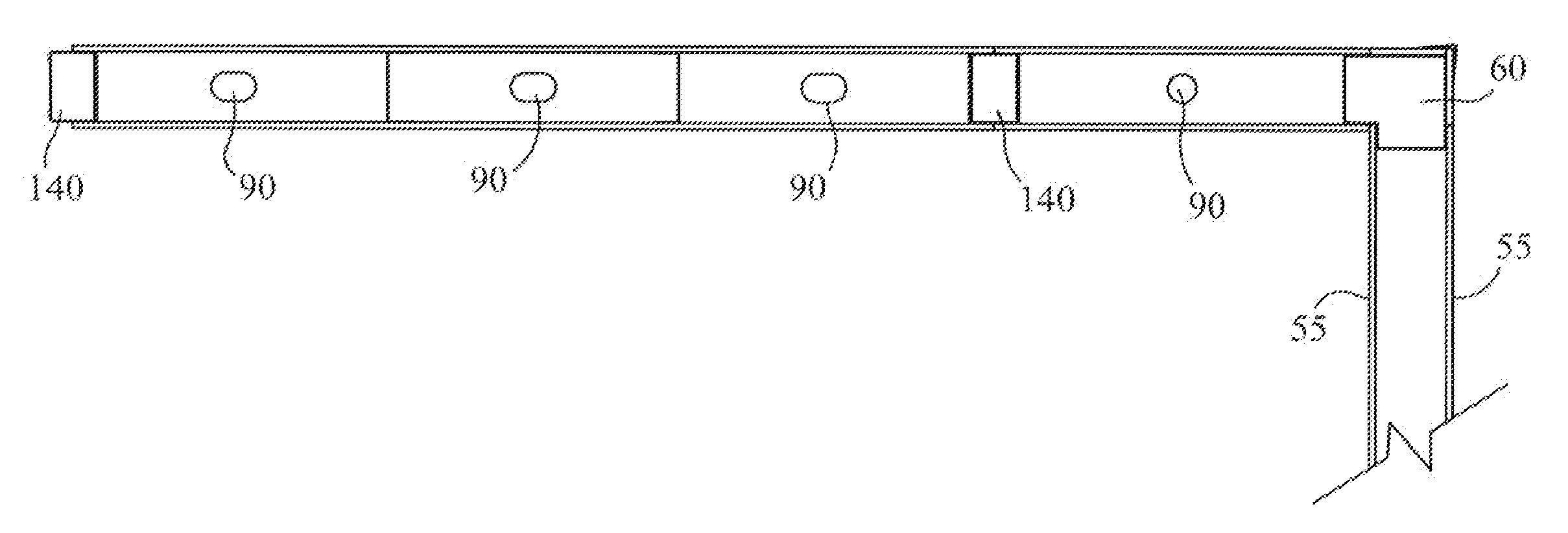
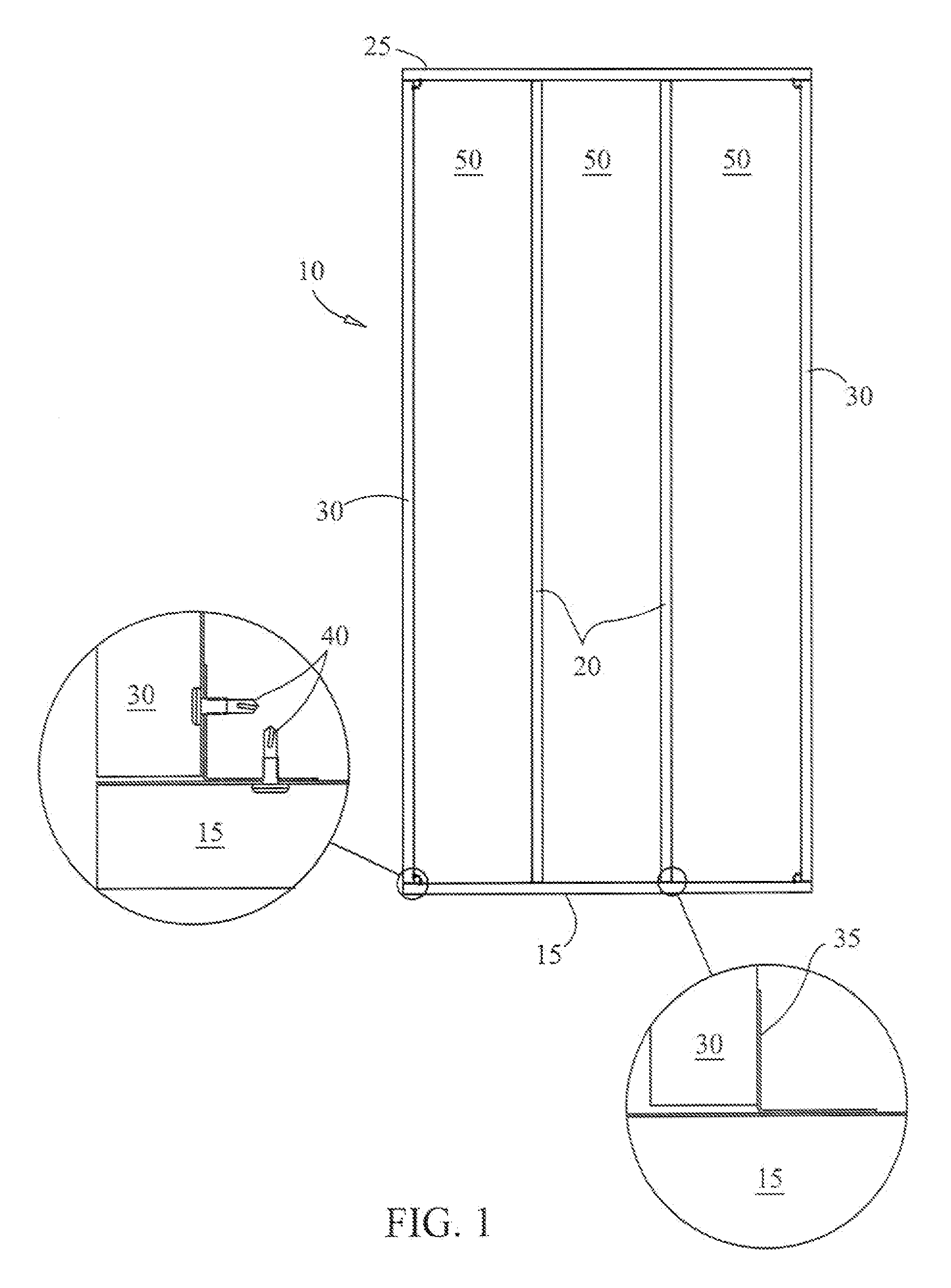
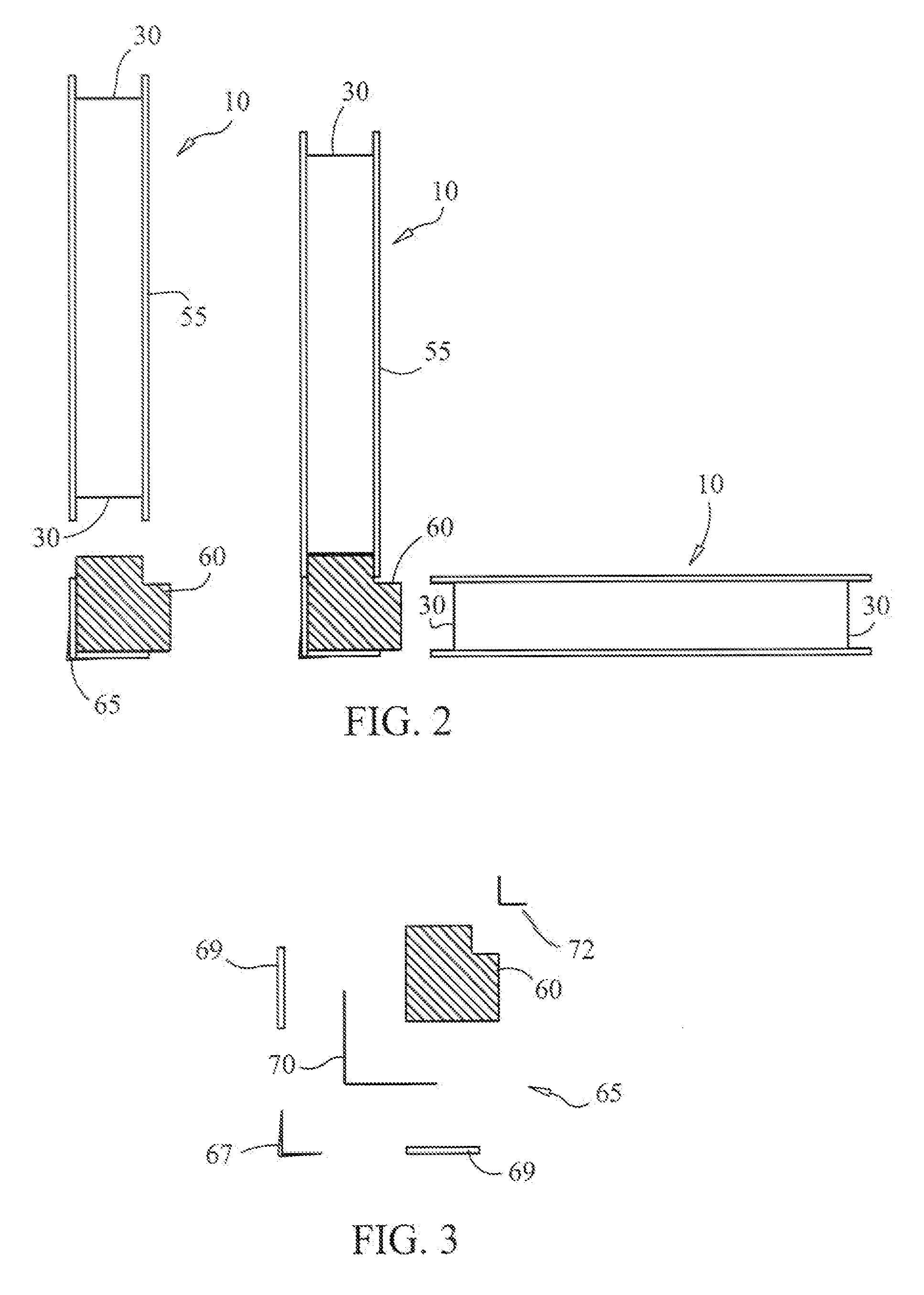
[0050] Referring now to FIG. 1, pre-fabricated wall panels 10 comprise a top plate 25 and bottom plate 15 including opposing end studs 30 to form the frame of wall panel 10. Intermediate studs 20 are interposed between ends studs 30. Foam inserts 50 are disposed within wall panel 10 and are adaptable to fit between the studs of wall panel 10. Foam inserts 50 provide support of wall panel 10 against inwardly directed force, insulation against heat transfer, vertical added load support, racking strength support, and integral chases for electrical wiring, plumbing piping and drains, HVAC duct placement, and specially system installations such as security, sound and computer. Screw...


PUM


Abstract

The present invention is a method and system for constructing pre-fabricated buildings. Wall panels are provided wherein each wall panel has a plurality of vertically disposed channel-shaped metal studs equidistantly disposed between a bottom plate and top plate. A substantially rigid foam insert is between each of the channel-shaped metal studs of a wall panel to provide insulation and structural support to the wall panel. The foam inserts each have an aperture forming a conduit vertically disposed within the foam insert. An interior spline is inserted between adjacent wall panels and provides the mechanical connection to secure the wall panels together. The interior spline comprises rigid foam with a pair of steel facing adhered on opposing faces of the spline.

Description

CROSS-REFERENCE TO RELATED APPLICATIONS [0001] This application claims the benefit of U.S. Provisional Application No. 60 / 754,110 filed Dec. 27, 2005. The disclosure of the provisional application is incorporated herein by reference.BACKGROUND OF THE INVENTION [0002] 1. Field of the Invention [0003] The present invention relates generally to building construction, and more specifically to a method and system for efficiently and economically constructing pre-fabricated residential and commercial buildings. [0004] 2. Description of the Prior Art [0005] Construction costs and quality of manufacture are major problems in the building trades. Many building systems have been proposed and used by others to cut costs and improve quality. Those prior art systems usually have some form of panelized pre-fabricated wall segment design. Many of such systems are in use worldwide. The shortcomings of the prior art pre-fabricated structures include, but are not limited to, inadequacies in the conne...

Claims


Application Information

Patent Timeline
Patent Type & Authority Applications(United States)
IPC IPC(8): E04B2/00E04C1/00
CPCE04B1/14E04B1/6145F24F11/0001E04C2/521E04B2001/6195
Inventor PAYNE, WILLIAMPAYNE, PATRICIA
Owner SUNSET MARKETING
Why Eureka
Try Eureka