Low friction coatings for dynamically engaging load bearing surfaces

a load bearing surface and low friction technology, applied in coatings, mechanical equipment, transportation and packaging, etc., can solve the problems of significant valve torque increase, loss of some mass and lubricating properties, and unstable price of expensive greases

Active Publication Date: 2007-07-19
VETCO GRAY LLC
View PDF22 Cites 60 Cited by
  • Summary
  • Abstract
  • Description
  • Claims
  • Application Information

AI Technical Summary

Benefits of technology

[0018] The method can also include the step of applying a lubricant to the coating after the coating is applied to the hardened engaging face. Prior to the hardening step, the method can include the step of texturing the engaging surface being hardened to

Problems solved by technology

Additionally, only very expensive greases are stable to temperatures above 400 F and may lose some of their mass and lubricating properties.
The loss of lubrication at high temperatures leads to significant increases in valve torques and may lead to the galling of the mating surfaces.
Some polymer type coatings have been used on gate valves as well, but suffer from insufficient load bearing capacity and ductility especially at elevate

Method used


Image

  • Low friction coatings for dynamically engaging load bearing surfaces
  • Low friction coatings for dynamically engaging load bearing surfaces
  • Low friction coatings for dynamically engaging load bearing surfaces

Examples


Embodiment Construction

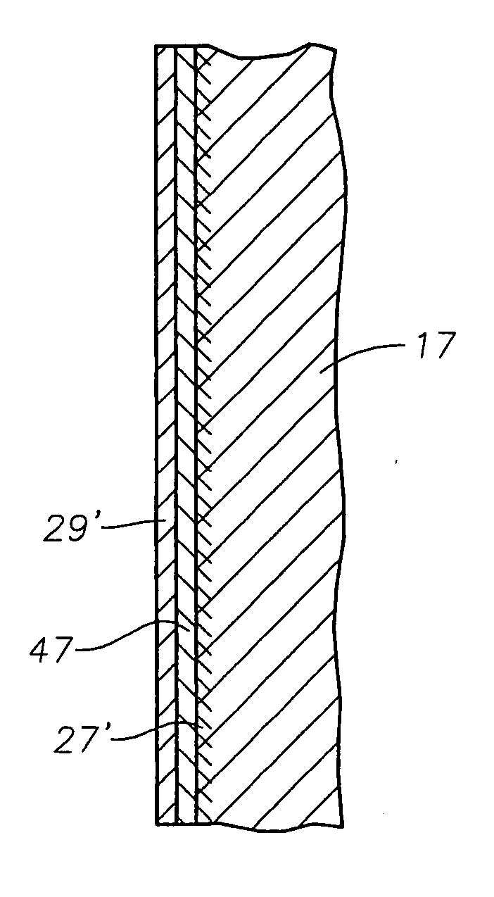
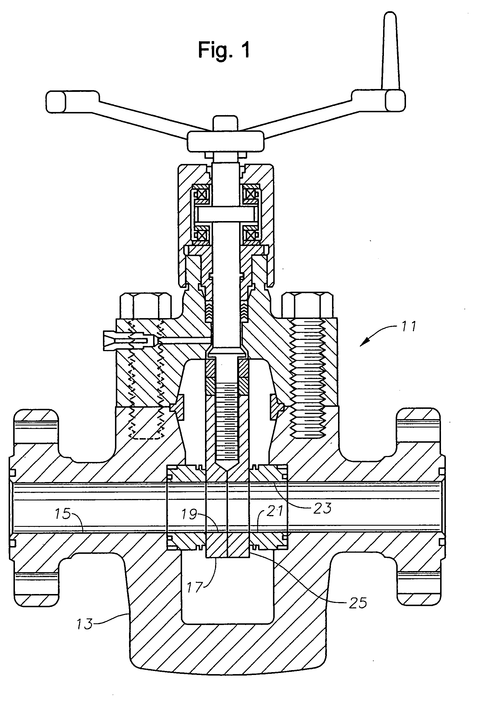
[0026] Referring to FIG. 1, gate valve 11 has a body 13 and a flow passage 15 that extends transversely through body 13. Valve 11 has a gate 17 with a hole 19 therethrough. Gate 17 is shown in the open position. The gate valve 11 shown in FIG. 1 is a non-rising-stem type valve, but the valve 11 may alternatively be a rising-stem type valve. Also shown in FIG. 1 are ring-shaped valve seats 21, which have holes 23 that register with the flow passage 15 of the valve. Gate valve 11 is shown as a split gate type having two separate slabs, but it could alternatively be a single slab type.

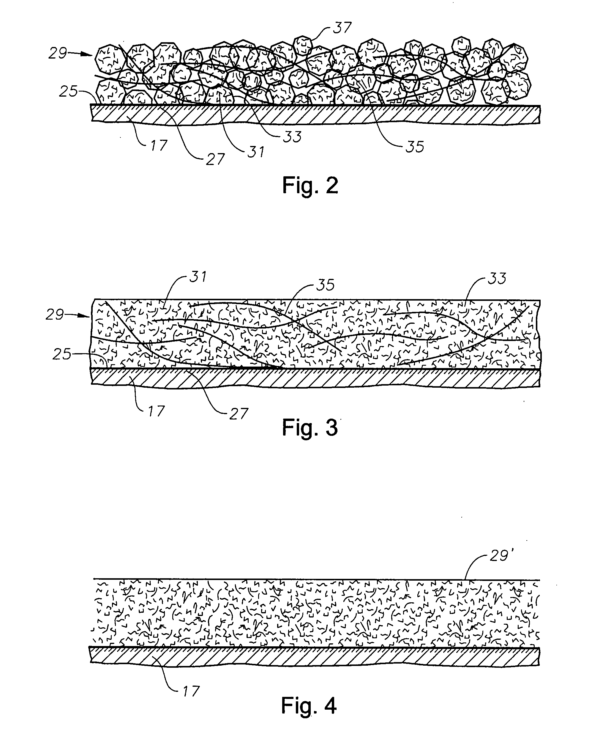
[0027] When gate 17 is in the open position, the hole 19 of the gate 17 registers with flow passage 15 of the valve 11, thereby allowing flow through the valve. When the gate is closed, the hole 19 no longer registers with the flow passage 15. The gate 17 has an engaging face 25 on each side that interfaces with seats 21. While gate 17 is closed, typically pressure in the flow passages 15 creates a subst...


PUM

PropertyMeasurementUnit
Thicknessaaaaaaaaaa
Thicknessaaaaaaaaaa
Lengthaaaaaaaaaa

Abstract

A gate valve has a body, the body having a cavity and a flow passage intersecting the cavity. A seat ring is mounted to the body at the intersection of the flow passage and the cavity, the seat ring having an engaging face. A gate in the cavity has an engaging face that slidingly engages the face of the seat ring while being moved between open and closed positions. A friction-resistant coating is on at least one of the faces.

Description

RELATED APPLICATIONS [0001] This continuation-in-part patent application claims the benefit of co-pending, provisional patent application U.S. Ser. No. 11 / 214,433, filed Aug. 29, 2005, which claimed the benefit of then co-pending, provisional patent application U.S. Ser. No. 60 / 605,176, filed Aug. 27, 2004, which are both hereby incorporated by reference in their entireties.BACKGROUND OF THE INVENTION [0002] 1. Field of the Invention [0003] The invention relates generally to low friction coatings formed on load bearing surfaces that slidingly engage each other, such as a gate and seat ring of a gate valve for a wellhead assembly. [0004] 2. Background of the Invention [0005] Gate valves are used when a straight-line flow of fluid and minimum flow restriction are required. When the valve is wide open, the gate is drawn into the opposite end of the valve cavity. The gate has an opening for flow through the valve the same size as the pipe in which the valve is installed. The valve provi...

Claims


Application Information

Patent Timeline
IPC IPC(8): F16K3/00
CPCF16K3/02F16K3/0236F16K3/0263Y10T137/7036
Inventor HUNTER, RICK C.
Owner VETCO GRAY LLC
Why Eureka
Try Eureka