Method and device for optical recording onto optical disc medium

a technology of optical disc and recording method, which is applied in the field of optical recording method and optical recording apparatus, can solve the problems of increasing the error ratio during reproduction, heat interference, and the inability to largely increase the recording linear density, and achieve the effect of improving the reliability of recording/reproducing operation

Inactive Publication Date: 2007-07-19
PANASONIC CORP
View PDF12 Cites 40 Cited by
  • Summary
  • Abstract
  • Description
  • Claims
  • Application Information

AI Technical Summary

Benefits of technology

[0028] As described above, with the optical recording method according to the present invention, marks to be recorded are classified by mark length and preceding or succeeding space lengths and the position of the second pulse edge counted from the end portion of a recording pulse train for recording each mark is shifted by an amount of edge shift dTF2 and / or dTE2 depending on the result of the aforementioned classification to adjust the recording pulse signals. This enables accurately controlling the starting end position and the ending end position of the mark to be formed on the optical disc medium. Further, the pulse edge is adjusted depending on the preceding or succeeding space lengths as well as on the mark length of the to-be-recorded mark, thus controlling the starting end position and the ending end position of the mark more accurately in consideration of inter-code interferences. This can improve the reliability of the recording / reproducing operation and realize miniaturization of the information recording apparatus and the recording medium at the same time.

Problems solved by technology

However, the method of increasing the recording linear density will cause the problem of the S / N ratio of reproducing signals, thus making it impossible to largely increase the recording linear density.
In the case of reducing the lengths of to-be-recorded marks and spaces in order to increase the recording density, particularly if the space lengths are made small, this will cause heat interferences, that is, heat of the ending end portion of a recorded mark may be transferred through the space region to affect the temperature rise at the starting end portion of the next mark or heat of the starting end portion of a recorded mark may affect the cooling process at the ending end portion of the previously-formed mark.
Prior-art recording methods have had the problem that the occurrence of heat interferences causes fluctuations of mark edge positions thereby increasing the error ratio during reproduction.
Furthermore, even when marks and spaces are formed on a disc to have accurate lengths, there may be caused the problem that the detected edge positions of short marks and spaces are deviated from ideal values during reproduction, due to the frequency characteristics of the reproducing optical system which depend on the size of the light spot.
There has been the problem that when the sizes of marks and spaces are smaller than the light spot, significant inter-code interferences are caused to increase jitter during reproduction, thus increasing the error ratio.
Namely, there has been the problem that marks are formed to be teardrop shapes and thus normal marks cannot be formed due to excessive amounts of heat injection.
Further, when minute marks have been formed during the mark forming process, marks having minimum mark lengths cause significant inter-code interferences.
When the inter-code interferences in the reproducing system are eliminated by increasing the boost value of the equalizer, noise components in high-frequency regions are increased, thus making it impossible to provide preferable jitter.
However, in the case of a recordable-type optical recording medium employing an inorganic material, the formation of marks have irreversible characteristics and thus includes no re-crystallization process of the recording film, which makes it impossible to adjust mark ending end positions by adjusting the widths of cooling pulses, in some mediums.
In the case of such mediums, jitter at the mark ending end positions will be increased, thus causing increases of the error ratio of reproducing signals.
As described above, the aforementioned prior-art techniques cannot enable the formation of marks with sufficient accuracy during high-density recording and consequently cannot realize sufficient recording surface densities and sufficient reliability.

Method used


Image

  • Method and device for optical recording onto optical disc medium
  • Method and device for optical recording onto optical disc medium
  • Method and device for optical recording onto optical disc medium

Examples


first embodiment

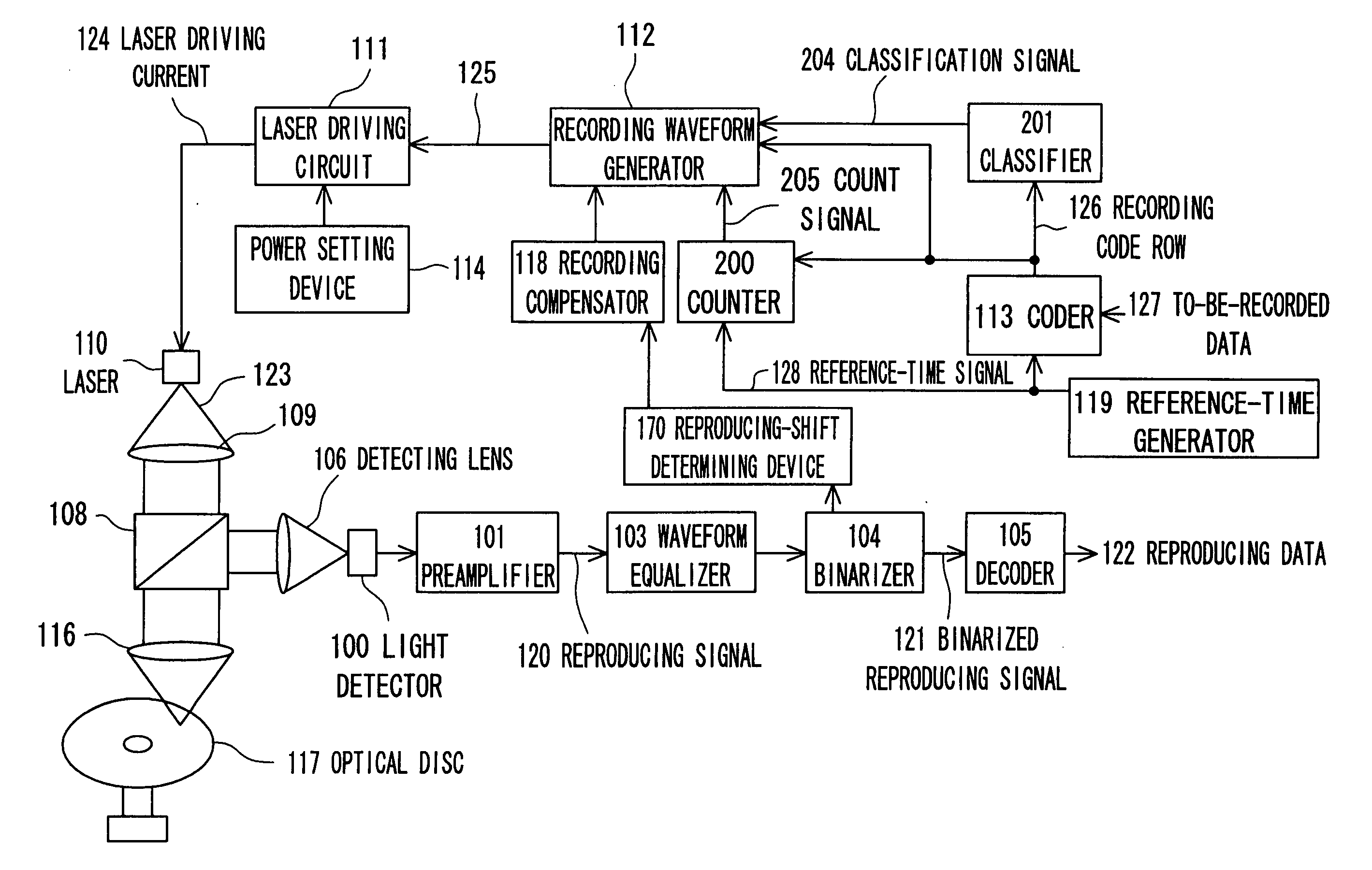
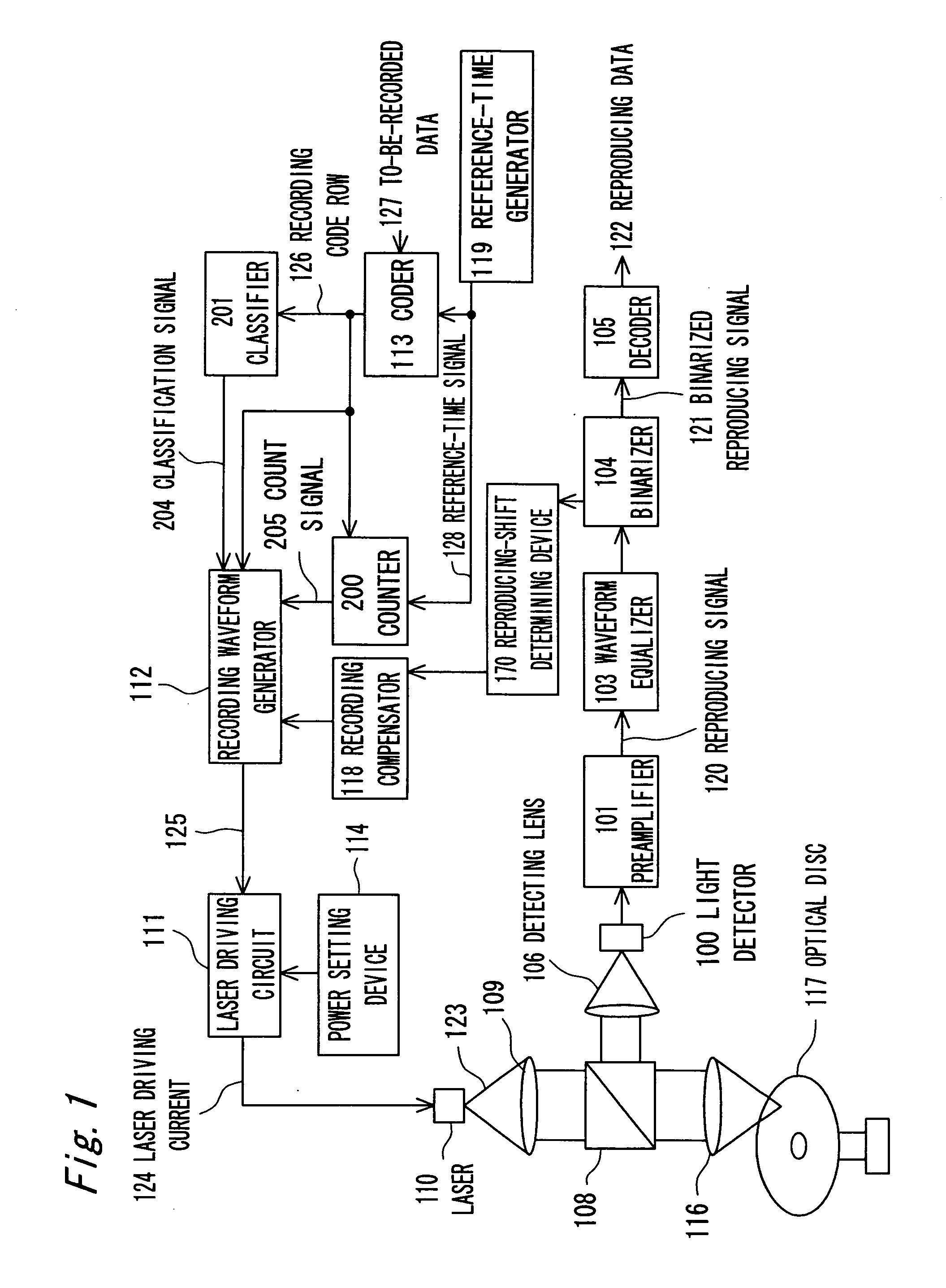
[0045]FIG. 1 is a block diagram illustrating the structure of an optical recording / reproducing apparatus according to the first embodiment of the present invention. This optical recording / reproducing apparatus includes, as a recording system, a coder 113, a reference-time generator 119, a counter 200, a classifier 201, a recording waveform generator 112, a recording compensator 118, a laser driving circuit 111, a power setting device 114, a laser 100 and an optical system including an objective lens 116. Further, this optical recording / reproducing device includes, as a reproducing system, the optical system including a detecting lens 106, a light detector 100, a preamplifier 101, a waveform equalizer 103, a binarizer 104, a decoder 105, and a reproducing-shift determining device 170. Further, the aforementioned optical system includes a collimating lens 109 and a half mirror 108, in addition to the objective lens 116 and the detecting lens 106.

[0046] First, the respective component...

second embodiment

[0102]FIG. 9 is a timing chart illustrating the relationship between the mark lengths of marks to be recorded and the recording pulse signals 125, in an optical recording method according to the second embodiment of the present invention. This optical recording method is different from the optical recording method according to the first embodiment in that the width Tlp of the last pulse at the peak power level (Pw) is adjusted in accordance with the result of classification of marks by mark length and succeeding space length. As the width of the last pulse Tlp, a total of 2*4=8 types of values (o1 to o8) are defined for the mark lengths of to-be-recorded marks which are classified into two types of mark lengths 3T and 4T and more and for the preceding space lengths classified into four types of spacing lengths 2T, 3T, 4T and 5T and more, as represented in the following Table. 15.

TABLE 15The mark lengthTlp3T>=4TThe preceding space length2To1o23To3o44To5o6>=5T    o7o8

[0103] By class...

third embodiment

[0104]FIGS. 10A to 10J are timing chart illustrating the relationship between the mark lengths of marks to be recorded and the recording pulse signals 125, in an optical recording method according to the third embodiment of the present invention. This optical recording method is different from the optical recording method according to the first embodiment in that the recording pulse signals 125 have waveforms in which the number of middle pulses is not proportional to the mark length value. According to the optical recording method, as illustrated in FIGS. 10C to 10J, the recording pulse signals for marks having mark lengths of 2Tw, 3Tw and 4Tw have a single pulse at the peak power level. The recording pulse signals 125 for marks having mark lengths of 5Tw and 6Tw have two pulses at the peak power level. The recording pulse signals 125 for marks having mark lengths of 7Tw and 8Tw have three pulses at the peak power level. The recording pulse signal 125 for a mark having a mark lengt...


PUM

PropertyMeasurementUnit
frequencyaaaaaaaaaa
linear speedaaaaaaaaaa
wavelengthaaaaaaaaaa

Abstract

There is provided an optical recording method for directing a recording pulse train to an optical disc medium to form marks thereon and for recording information as information about the edge positions of said marks and the spaces between marks, the recording pulse train having been created by modulating laser light into plural power levels. The method includes: coding to-be-recorded data into coded data consisting of the combination of marks and spaces; classifying said marks within said coded data on the basis of the mark length and the preceding or succeeding space lengths of the marks; shifting the position of the second pulse edge counted from the end portion of the recording pulse train for forming said marks, depending on the result of said classification, to adjust said recording pulse train; and directing said recording pulse train to the optical disc medium to form said marks thereon.

Description

TECHNICAL FIELD [0001] The present invention relates to optical recording methods and optical recording apparatuses for recording information onto an optical disc medium by directing laser light thereto to form marks thereon. BACKGROUND ART [0002] Optical discs such as DVD-RAMs are phase-change discs including amorphous marks which have been formed on the recording film by directing laser light thereto and controlling the laser power during heating for changing the cooling ratio of the recording film. In order to increase the information transfer rate during recording and reproducing onto and from these optical disc mediums, the recording linear density may be increased or the scanning speed of a light spot over the recording medium can be increased. In order to increase the recording linear density, mark lengths and space lengths themselves may be reduced or mark lengths and space lengths may be varied minutely to reduce the time intervals of detection of mark edge positions. Howev...

Claims


Application Information

Patent Timeline
Patent Type & Authority Applications(United States)
IPC IPC(8): G11B7/0045G11B7/006G11B7/126
CPCG11B7/00456G11B7/126G11B7/0062G11B7/0045
Inventor NAKAMURA, ATSUSHIMIYAGAWA, NAOYASU
Owner PANASONIC CORP
Why Eureka
Try Eureka