Microfluidic chips and assay systems

a technology of microfluidic chips and assay systems, applied in the field of microfluidics, can solve the problems of limiting the practicality with which the system can be utilized in various chemical or biological assays, affecting the efficiency of assays, and requiring repetitive manipulation in the world of assays, etc., and achieves the effects of convenient and rapid reconfiguration, avoiding the need for a second machine, and being convenient to opera

Active Publication Date: 2007-07-19
RHEONIX
View PDF8 Cites 122 Cited by
  • Summary
  • Abstract
  • Description
  • Claims
  • Application Information

AI Technical Summary

Benefits of technology

[0009]The system and methods described herein, in one embodiment, include a plastic microfluidic chip configured to process one or more reagents. The chip may comprise various microfluidic features including valves, pumps, channels and reservoirs. The micro-features are interconnected to allow various combinations of fluid flow patterns that can be user specified and tailored to a particular application. In particular, the chip allows for the transport of one or more reagents from respective reagent reservoirs on a reagent cartridge to multiple assay channels via a transport structure. The transport is directed by the automated operation of pneumatically driven pumps and valves. By coordinating the flow of reagent from the reagent reservoirs to the channels both spatially and temporally using the automated methods described herein, a user can efficiently perform biological immunoassays.
[0018]In another aspect, the porting device comprises a separate reagent chip including the inlet channels, the distribution valve and a plurality of reagent reservoirs. The reagent reservoirs are aligned with the inlet channels for introducing reagents to the distribution valve. The porting device also includes a ducting chip having the outlet channels disposed therein. The ducting chip is adapted to detachably couple to the reagent chip and the substrate for introducing the reagents from the reagent chip to the assay channels in the substrate. The separation of an application chip into several modules allows greater design and fabrication flexibility, the utilization of a variety of chip materials and the repetitive usage of the reagent cartridge.
[0024]In another aspect, a heating element is coupled to the microfluidic chip for controlling the assay temperature for enhanced assay repeatability, speed and sensitivity.

Problems solved by technology

However, existing microfluidic systems lack adequate mechanisms for allowing controlled manipulation of multiple fluids except via prescribed flow patterns, hence limiting the practicality with which the systems can be utilized in various chemical or biological assays.
This is because real-world assays often require repetitive manipulation of different reagents under continuously varying conditions.
Moreover, many existing microfluidic devices are restricted for one specific use and cannot be easily adapted or customized for other applications without being completely redesigned.
These devices lack modularity, and therefore cannot share common device components that allow one design to perform multiple functions.
This lack of flexibility leads to increased production costs as each use requires the production of a different system.
Furthermore, many existing microfluidic systems lack any means for straightforward end-point assays that are able to easily detect interactions or existence of analysts resulting from the assays.
In one embodiment, an entire microfluidic chip suitable for portable immunoassay is made from polystyrene, which results in extremely low fabrication costs.

Method used


Image

  • Microfluidic chips and assay systems
  • Microfluidic chips and assay systems
  • Microfluidic chips and assay systems

Examples


Embodiment Construction

[0049]The invention, in various embodiments, provides microfluidic chips, systems and methods. The following detailed description refers to the accompanying drawings. The following detailed description does not limit the invention. Instead, the scope of the invention is at least the scope defined by the appended claims and equivalents.

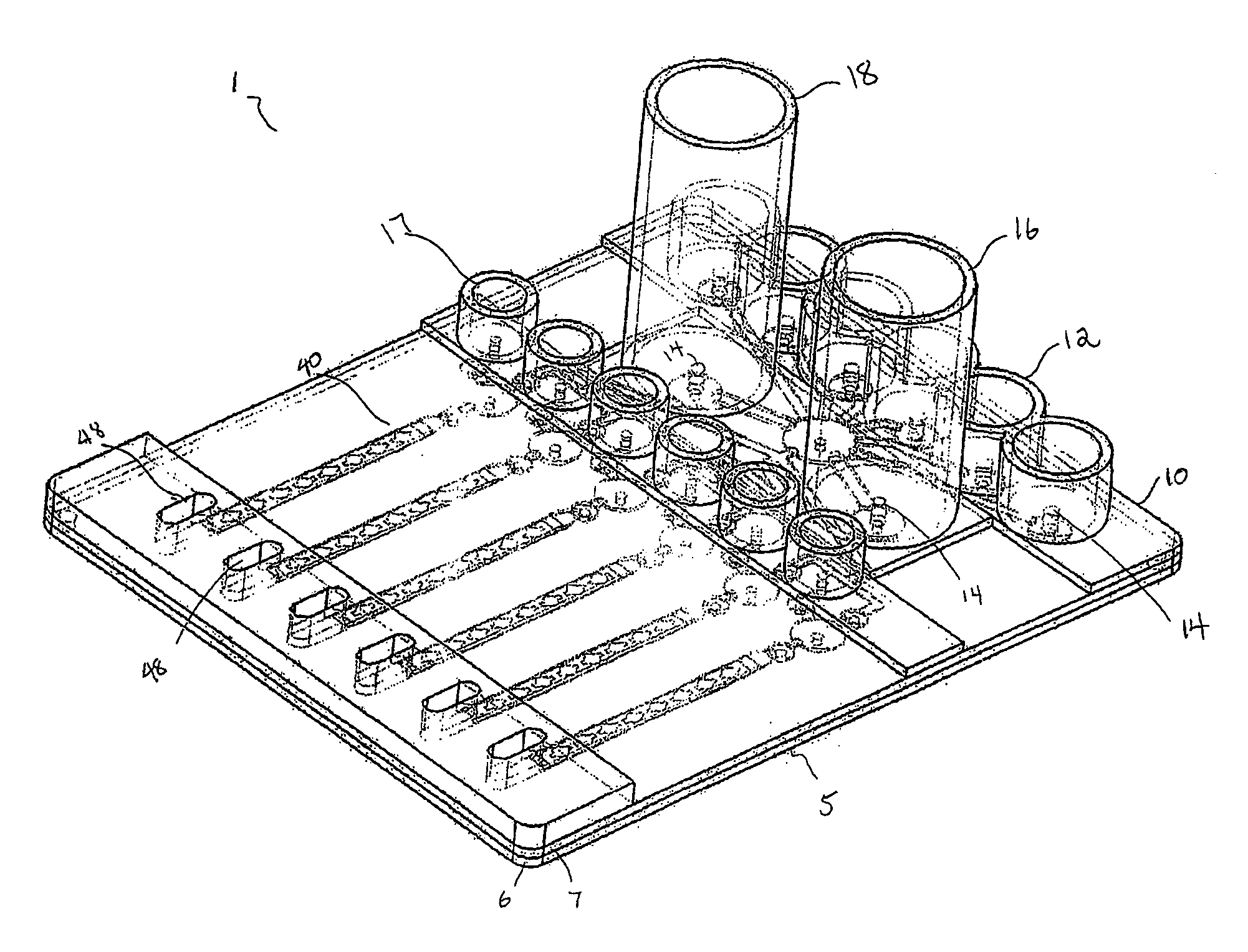
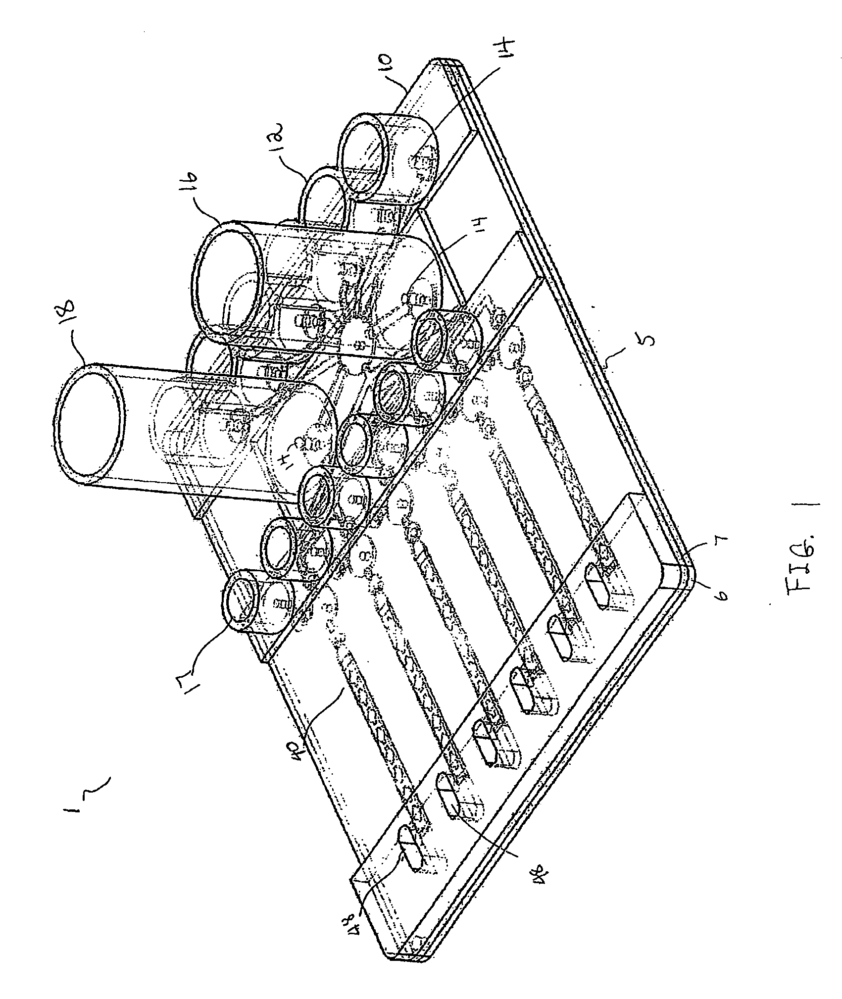
[0050]FIG. 1 illustrates a microfluidic system 1 that includes an assay chip 5 and a cartridge 10 disposed on the chip 5 along a width of the chip 5. The cartridge 10 includes a plurality of reagent reservoirs 12 having side walls that define chambers to hold fluid reagents. The chip 5 includes a buffer reservoir 16 having a cylindrical sidewall to hold a washing buffer, a plurality of shuttle reservoirs 17 adapted to hold reagents during an assay operation, and a waste reservoir 18 adapted to hold used reagents and used buffer after the assay operation. The chip 5 also includes a plurality of inlet valves 14 positioned to align with the various reserv...


PUM


Abstract

The systems and methods described herein include a microfluidic chip having a plurality of microfeatures interconnected to provide a configurable fluid transport system for processing at least one reagent. Inserts are provided to removably interfit into one or more of the microfeatures of the chip, wherein the inserts include sites for interactions with the reagent. As will be seen from the following description, the microfluidic chip and the inserts provide an efficient and accurate approach for conducting parallel assays.

Description

CROSS-REFERENCE TO RELATED APPLICATIONS[0001]This application claims priority to Provisional Application No. 60 / 760,552, filed on Jan. 19, 2006, and incorporated herein by reference in its entirety.FIELD OF THE INVENTION[0002]The systems and methods described herein generally pertain to the field of microfluidics. In particular, these systems and methods pertain to microfluidic diaphragm structures, microfluidic chips, portable automated microfluidic reagent processing systems, and fabrication and use thereof.BACKGROUND AND OBJECTS OF THE INVENTION[0003]“Microfluidics” generally refers to systems, devices, and methods for processing small volumes of fluids. Because microfluidic systems can integrate a wide variety of operations to manipulating fluids, such as chemical or biological samples, these systems have many application areas, such as biological assays (for, e.g., medical diagnoses and drug delivery), biochemical sensors, or life science research in general.[0004]One type of m...

Claims


Application Information

Patent Timeline
Patent Type & Authority Applications(United States)
IPC IPC(8): B01L3/00
CPCB01L3/5025Y10T436/117497B01L3/502738B01L7/00B01L2200/026B01L2200/027B01L2200/028B01L2200/04B01L2200/0621B01L2200/0684B01L2200/10B01L2200/16B01L2300/0654B01L2300/0816B01L2300/0864B01L2300/0867B01L2300/0874B01L2300/0887B01L2300/1827B01L2400/0481B01L2400/0622B01L2400/0633B01L2400/0655B01L2400/0666B01L2400/084F04B43/043F16K99/0001F16K99/0015F16K99/0059F16K2099/0084F16K2099/0094B01L3/502715G01N1/28Y10T436/2575B01L3/50273Y10T137/0324F04B43/14B81B1/00B01L3/00B81B7/00B01F25/00
Inventor ZHOU, PENGYOUNG, LINCOLN
Owner RHEONIX
Why Eureka
Try Eureka