Method and Apparatus for Measuring Blood Volume, and Vital Sign Monitor Using the Same

a technology of blood volume and vital signs, which is applied in the direction of catheters, medical science, diagnostics, etc., can solve the problems of high invasiveness of catheter insertion in the thermodilution method, inability to allow continuous measurements, and inability to measure intermittently, so as to reduce the suffering of patients and avoid infection.

Active Publication Date: 2007-07-19
NIHON KOHDEN CORP
View PDF2 Cites 12 Cited by
  • Summary
  • Abstract
  • Description
  • Claims
  • Application Information

AI Technical Summary

Benefits of technology

[0017] It is therefore an object of the invention to provide a blood volume measurement method, in which variation in the hemodynamics of a patient can be monitored invasively and continuously at all times, an aid of a skilled medical person in the insertion of a catheter or the like is not needed, suffering of the patient is lessened, and there is no risk of infection because it is non-invasive.
[0018] It is also an object of the invention to provide a blood volume measurement apparatus for embodying the above method with an inexpensive configuration.

Problems solved by technology

The thermodilution method involves a problem in that the measurement is intermittent and continuous measurements are not allowed.
Further, insertion of a catheter in the thermodilution method is highly invasive for a patient and involves a risk of infection and the like.
Recently, a method based on continuous measurements has also been developed in the thermodilution method, however, the method still requires insertion of a catheter, and the above-described problems in connection with the insertion of a catheter cannot be solved.
The dye dilution method also has a problem in that continuous measurements are impossible.
Further, the method requires a skilled medical person in the measuring process.
The ultrasound method imposes a burden of stress on a patient because a transducer is attached transesophageally.
Recently, a non-invasive measurement performed on the body surface has also been made available as a kind of the ultrasound method, but the continuous measurements are still impossible.
Considering the requirement for an aid of a medical person with advanced skill and the procedures being highly invasive for a patient, none of the methods described above can be conducted easily and continuously, and it is difficult to monitor the variation in the hemodynamics of a patient continuously at all times by these methods.

Method used


Image

  • Method and Apparatus for Measuring Blood Volume, and Vital Sign Monitor Using the Same
  • Method and Apparatus for Measuring Blood Volume, and Vital Sign Monitor Using the Same
  • Method and Apparatus for Measuring Blood Volume, and Vital Sign Monitor Using the Same

Examples


Embodiment Construction

[0047] The principle used in the invention for the measurement of the blood volume ejected by cardiac contraction (cardiac output) will be explained below.

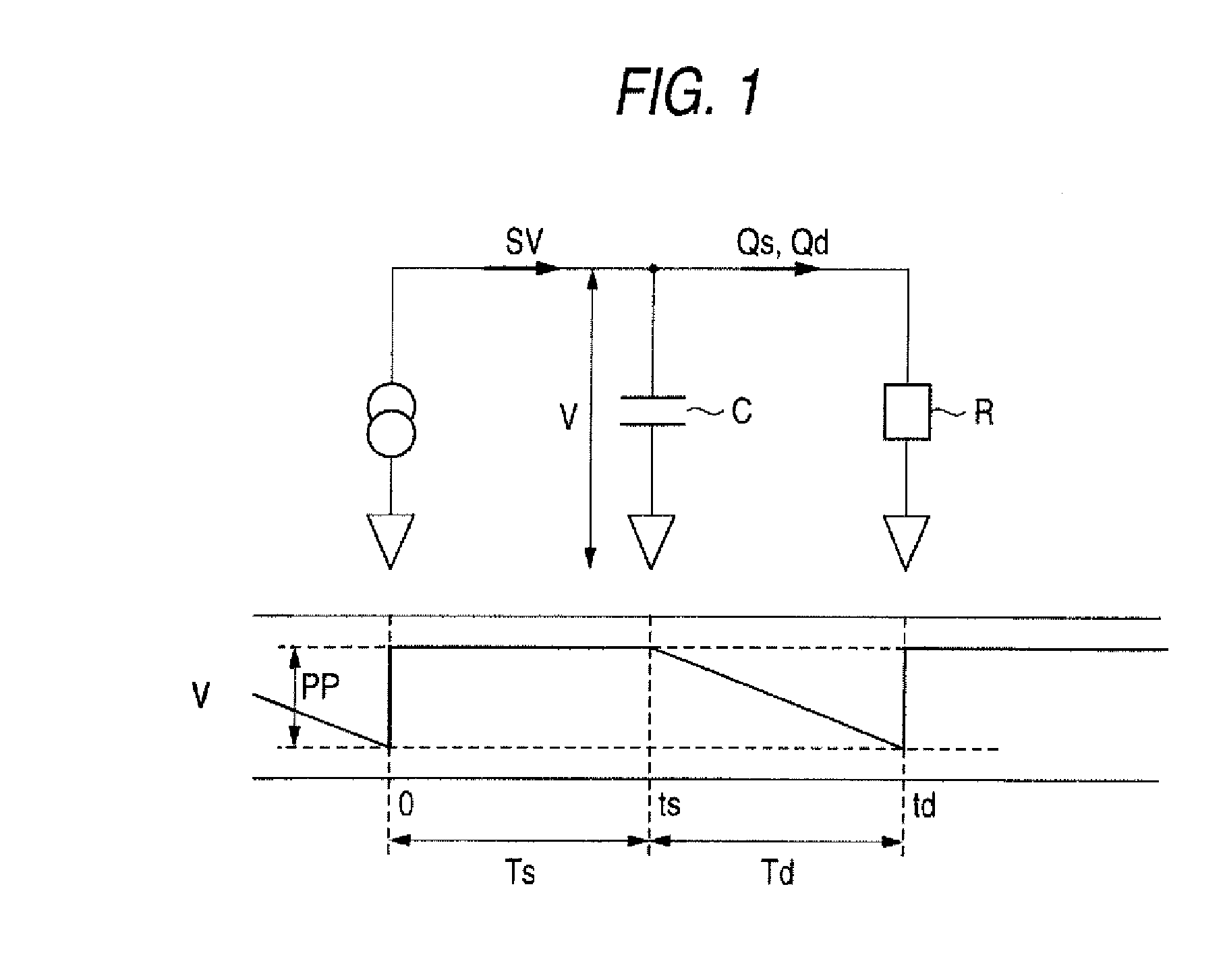
[0048] When the Windkessel model as shown in FIG. 1 is used, the influx flow volume to the aorta during a systole, that is, the flow volume (SV−Qs) obtained by deducting the efflux flow volume to the periphery during a systole Qs from the stroke volume SV, is represented by the product of the aortic compliance C with the pulse pressure PP (see Equation 1). In this specification, the term “pulse pressure” means a difference between the systolic blood pressure and the diastolic blood pressure.

SV−Qs=C·PP  (1)

[0049] The efflux flow volume to the periphery during a diastole Qd is the same as (SV−Qs). Further, Qs and Qd represent values obtained by dividing the systolic and diastolic arterial pressures V by the vascular resistance R and then multiplying by the systolic duration Ts and the diastolic duration Td, respectively. However,...


PUM


Abstract

A first member is adapted to measure an electrocardiogram of a patient. A second member is adapted to measure a peripheral pulse wave of the patient. A first calculator calculates a pulse wave propagation time (PWTT) and a heart rate (HR) of the patient based on the electrocardiogram and the peripheral pulse wave. A second calculator calculates a cardiac output (CO) of the patient with an equation of CO=(αK·PWTT+βK)·HR, where α, β and K are coefficients inherent to the patient.

Description

[0001] This is a divisional of application Ser. No. 11 / 094,228 filed Mar. 31, 2005. The entire disclosure of the prior application, application Ser. No. 11 / 094,228 is hereby incorporated by reference.BACKGROUND OF THE INVENTION [0002] The present invention relates to a method and an apparatus for measuring blood volume ejected by cardiac contraction, and a vital sign monitor using such method and apparatus. [0003] In medical facilities, variation in the hemodynamics of a patient in an operating room, an intensive care unit (ICU), an emergency room, a dialysis treatment room or the like needs to be monitored continuously as long as possible. [0004] Conventionally, monitoring of the variation in the hemodynamics of such a patient has been predominantly carried out by direct monitoring of a blood pressure. [0005] In a living body, a cardiac output and a vascular resistance are regulated such that the blood pressure of the centrum is limited within a predetermined range. [0006] Therefor...

Claims


Application Information

Patent Timeline
Patent Type & Authority Applications(United States)
IPC IPC(8): A61B5/04A61B5/02A61B5/0245A61B5/0285A61B5/029
CPCA61B5/0245A61B5/029A61B5/0285
Inventor SUGO, YOSHIHIROAKIYAMA, TAKESHIUCHIDA, KEISUKETAKEDA, SUNAO
Owner NIHON KOHDEN CORP
Why Eureka
Try Eureka