Rotating bed gasifier

a gasifier and rotating bed technology, applied in the direction of gasifier mechanical details, fuel gas production, combustible gas production, etc., can solve the problems of limiting the size of the gasifier which can be constructed, uneven gasification, and questionable primary energy generation, so as to reduce the size limitations, improve efficiency, and improve the effect of air flow

Inactive Publication Date: 2007-07-26
THIESSEN RANDALL J +1
View PDF11 Cites 24 Cited by
  • Summary
  • Abstract
  • Description
  • Claims
  • Application Information

AI Technical Summary

Benefits of technology

[0008] Another feature or advantage of the present invention is the provision of a gasifier which reduces the size limitations in which a gasifier fuel mixer can be built.
[0009] Another feature or advantage of the present invention is the provision of a gasifier that more uniformly heats the material being gasified to improve efficiency.
[0010] Another feature or advantage of the present invention is the provision of a gasifier that improves air flow to the fuel.
[0011] Another feature or advantage of the present invention is the provision of a gasifier that preferably includes a rotating bed, is economical to manufacture, durable in use and efficient in operation.
[0012] These and the other features or advantages of the present invention will be apparent from the specification and claims that follow.
[0013] One or more of the foregoing features or advantages may be achieved by a gasifier having a container with a top, sidewalls, and a bottom for facilitating the gasifying process. An open vertical shaft extends down from the top of the container and allows a downdraft or updraft of air to mix with fuel for the gasifying process. A rotating bed inside the container preferably located below the shaft receives the fuel; the bed rotates essentially perpendicular to the shaft.

Problems solved by technology

Steam boiler / combustor units are also well-known, though their use for primary energy generation has been questionable for some time, mainly because of the harmful resultant emissions.
One problem with fixed bed gasifiers is that there are inherent “hot spots” in the fuel, causing uneven gasifying.
This limits the size of the gasifier which can be constructed.
By creating too large a gasifier, these fingers or the shaft holding them bend and break during the agitation.
A problem with these vertically reciprocating beds and fixed bed gasifiers is that the larger the gasifier, the more chance for uneven heating inside the gasifier and thus poor gasifying of the fuel.

Method used


Image

  • Rotating bed gasifier
  • Rotating bed gasifier
  • Rotating bed gasifier

Examples


Embodiment Construction

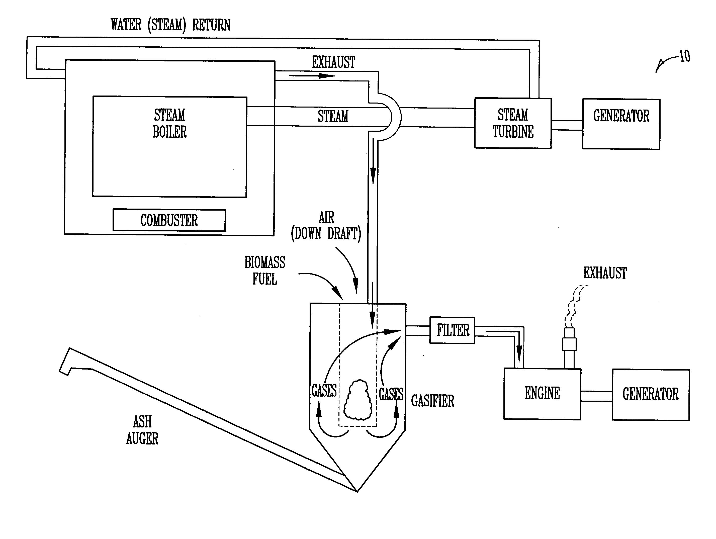
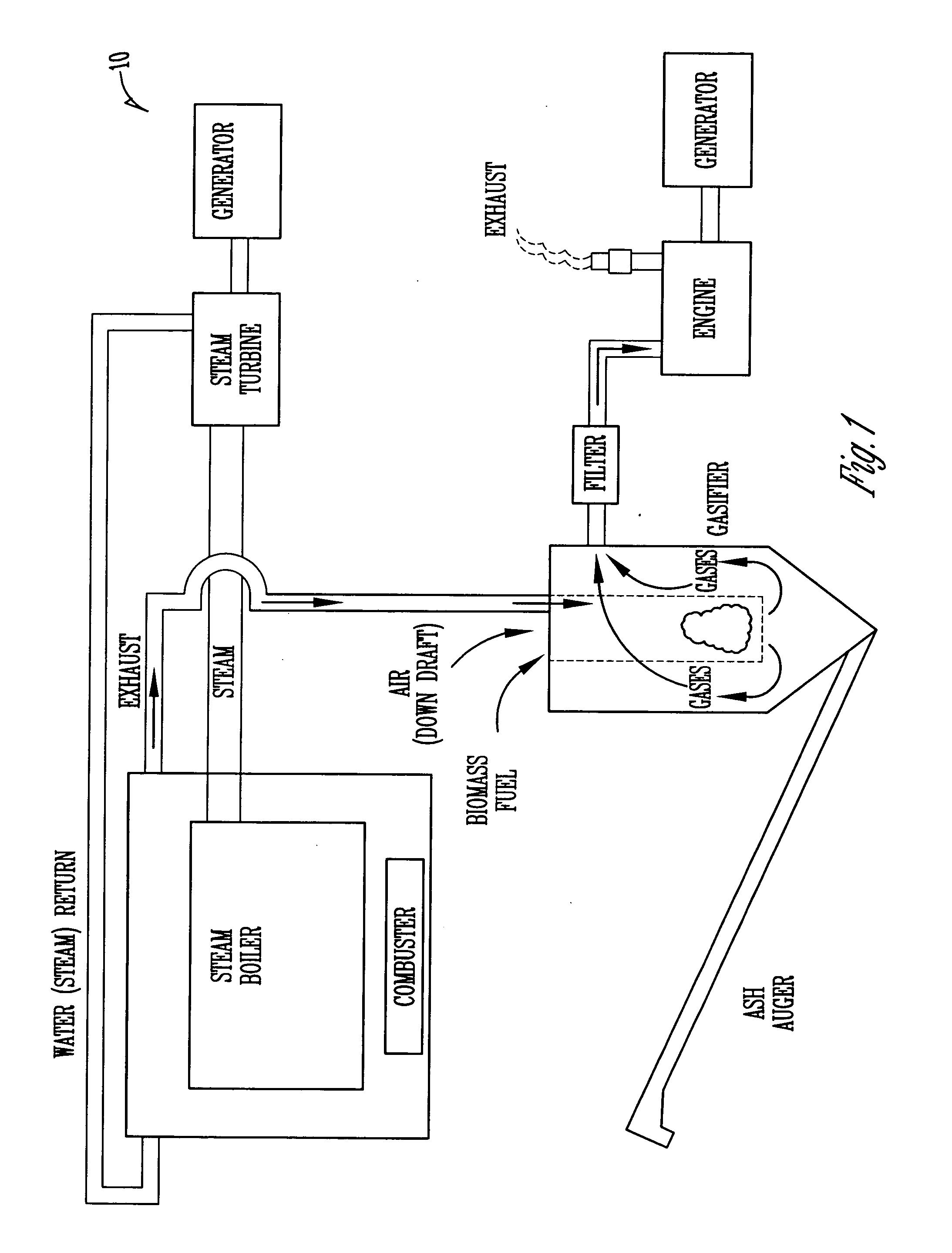
[0027] The present invention relates to a rotating bed gasifier. The present invention can be used in a system such as the system 10 as shown in FIG. 1. However, the present invention can be used in any type of system where a gasifier for gasifying solid fuels is desired.

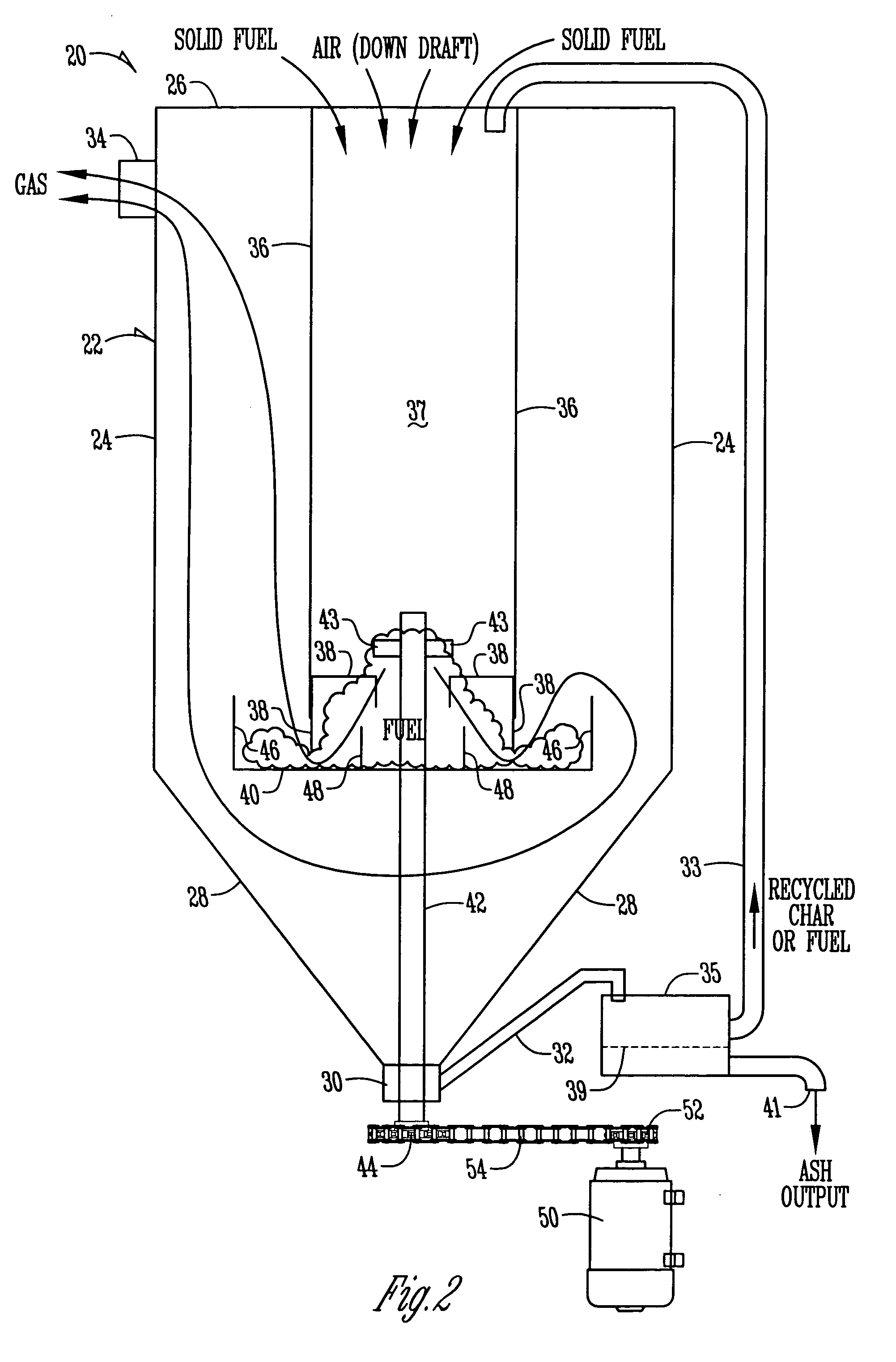
[0028] Referring now to FIG. 2, a cut away side view of one embodiment of a rotating bed gasifier assembly 20 is shown. The gasifier assembly 20 begins with a gasifier container assembly 22. The gasifier container assembly 22 generally has a cylindrical shaped sidewall 24. However, the sidewall 24 can be in any shape. Connected to the sidewall 24 is a top 26 and a bottom 28. Preferably, the bottom 28 is an inverted cone-shaped piece of metal to allow used ashes and overflow fuel or char to fall to a central point of an ash sump 30.

[0029] The ash sump 30 is connected to the bottom 28 of the gasifier container assembly 22 preferably is connected to an ash auger 32 for removing the fuel and ashes after they have been...


PUM

PropertyMeasurementUnit
diameteraaaaaaaaaa
bed rotationaaaaaaaaaa
energyaaaaaaaaaa

Abstract

The present invention includes a gasifier for gasifying fuels having a container with a top, sidewalls and a bottom for facilitating the gasifying process. One or more open vertical shafts extend downward inside the container for allowing a downdraft or updraft of air and fuel for the gasifying process. A rotating bed is preferably included inside the container and below the one or more shafts for receiving the fuel. The bed rotates essentially perpendicular to the shaft to facilitate even heating and gasifying of the fuel.

Description

BACKGROUND OF THE INVENTION [0001] The present invention relates generally to an apparatus for providing a more effective and efficient gasifier apparatus. More particularly, although not exclusively, the present invention relates to a rotating bed gasifier apparatus. [0002] Currently, there are many types of gasifier systems. Typically the gasification process is the primary energy generation means. Gasification generally takes materials, such as wood, coal, charcoal, agricultural residues, energy crops, municipal solid waste or other biomass materials, and gasifies them to make a “gas” used for power or electricity generation or other uses, such as heat production. A typical gasification system consists of a gasifier unit, a filtering system, and an energy converter. [0003] Steam boiler / combustor units are also well-known, though their use for primary energy generation has been questionable for some time, mainly because of the harmful resultant emissions. A steam boiler / combustor ...

Claims


Application Information

Patent Timeline
Patent Type & Authority Applications(United States)
IPC IPC(8): C10J3/68C10J1/207
CPCC10J3/005C10J2300/1807C10J3/34C10J3/42C10J3/84C10J3/86C10J2200/09C10J2300/0916C10J2300/093C10J2300/0956C10J2300/165C10J2300/1671C10J2300/1675C10J2300/1687C10J3/26
Inventor THIESSEN, RANDALL J.THIESSEN, LAVOY M. JR.
Owner THIESSEN RANDALL J
Why Eureka
Try Eureka