Process and device for coating strips

Inactive Publication Date: 2007-07-26
CIS SOLARTECHN
View PDF2 Cites 22 Cited by
  • Summary
  • Abstract
  • Description
  • Claims
  • Application Information

AI Technical Summary

Benefits of technology

[0044] The construction of large systems can be facilitated by dividing at least one of

Problems solved by technology

Many materials, however, cannot be electroplated at all or can be electroplated only with great difficulty.
Similar problems exist with ceramic materials (oxides, nitrides) such as SiOx, TiOx, Znx, AlN, and SiN.
In addition, strips which do not conduct electricity cannot be coated by the electroplating process.
A

Method used


Image

  • Process and device for coating strips
  • Process and device for coating strips
  • Process and device for coating strips

Examples


Embodiment Construction

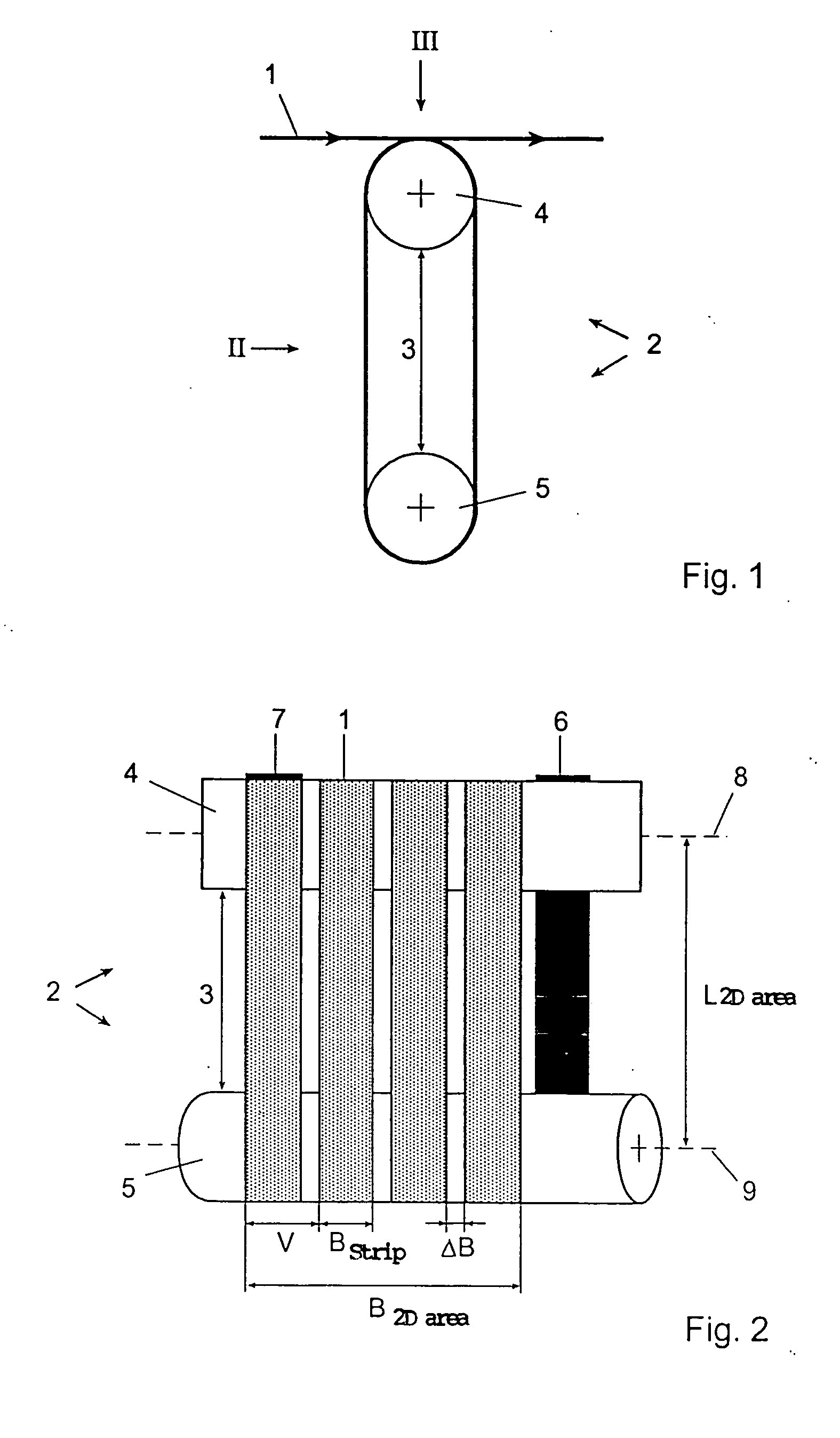
[0057] According to the embodiment shown in FIG. 1, a strip 1 to be coated is conducted over a strip guide 3, which is made up of two guide elements 4, 5 arranged a certain distance apart.

[0058]FIG. 2 shows a side view, which illustrates that the guide elements 4, 5 are designed as rolls, where the uncoated strip 1 is fed to the strip guide 2 in the area of a strip inlet 6, while the coated strip 1 is taken away in the area of a strip outlet 7. The longitudinal axes 8, 9 of the guide elements 4, 5 are a certain distance (L2Darea) apart. The individual loops of the strip are separated by gaps AB, and the complete set of loops passing around the guide elements 4, 5 extend over an effective width of B2Darea.

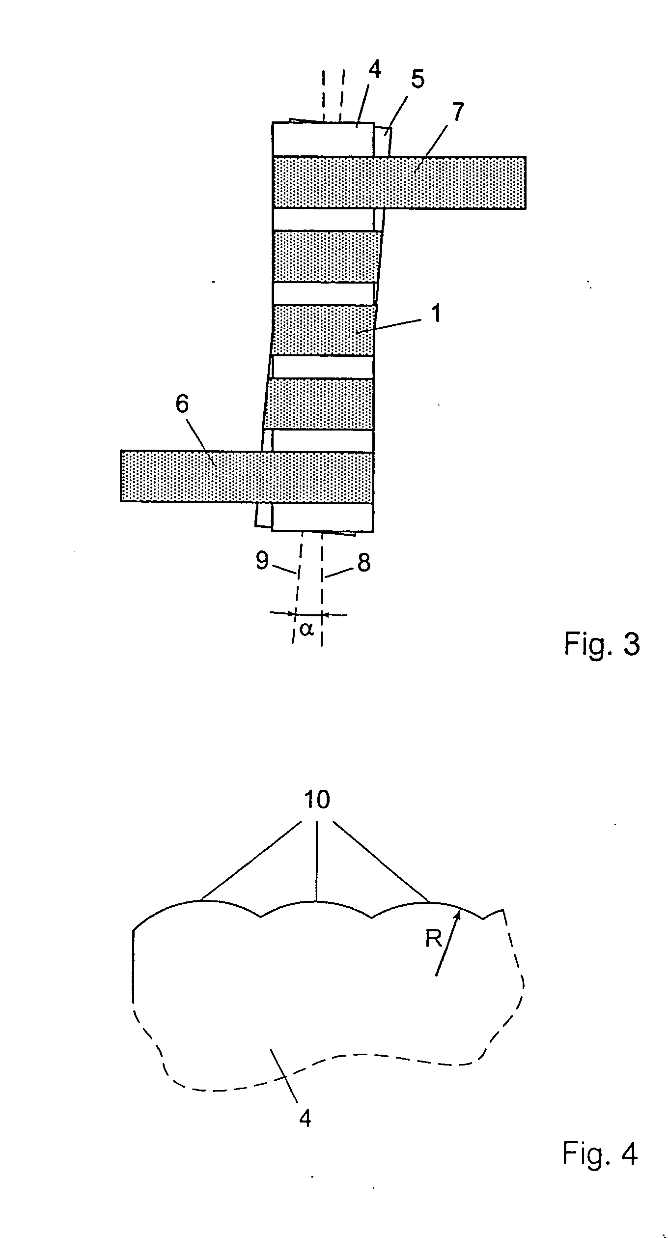
[0059]FIG. 3 shows the arrangement according to FIGS. 1 and 2 from above in viewing direction III. It can be seen that the longitudinal axes 8, 9 are arranged at a slant to each other at an angle α.

[0060]FIGS. 1-3 show a strip guide arrangement, in which the strip 1 to be coated ...


PUM

PropertyMeasurementUnit
Angleaaaaaaaaaa
Angleaaaaaaaaaa
Angleaaaaaaaaaa

Abstract

A process and a device for coating a strip in which the strip is transported along a strip guide inside a coating chamber. At least two guide elements of the strip guide are positioned a certain distance apart, their longitudinal axes being arranged at a slant to each other in such a way that the distance between the guide elements varies along the longitudinal axes. The strip is conducted along the guide elements inside the coating chamber in such a way that at least two sections of the strip are traveling essentially adjacent to each other as they are being coated.

Description

BACKGROUND OF THE INVENTION [0001] 1. Field of the Invention [0002] The present invention relates to a strip-coating process in which the strip is transported inside a coating chamber along a strip guide. [0003] The invention also relates to a device for coating a strip, wherein the device is equipped with a strip guide in a coating chamber. [0004] 2. Description of the Related Art [0005] Narrow metal strips with widths in the range of 1-10 cm are coated at low cost by electroplating. For example, solderable substrates can be produced by plating narrow strips of copper with tin. Many materials, however, cannot be electroplated at all or can be electroplated only with great difficulty. Such materials include Ti, V, Mn, Zr, Nb, Mo, Ta, and W. This is described, for example, on page 22 of Tabellenbuch der Galvanotechnik [Book of Electroplating Tables] by J. N. M. Unruh (ISBN 3-87480-165-9, Eugen G. Leutze Verlag, 7th edition, 2001). Similar problems exist with ceramic materials (oxides...

Claims


Application Information

Patent Timeline
IPC IPC(8): C23C16/00C23C14/00
CPCC23C14/562H01L31/18C23C16/545
Inventor SCHNEIDERS, HOLGERTHYEN, RUDOLFRECHID, JUAN
Owner CIS SOLARTECHN
Why Eureka
Try Eureka