Intake port for 4-cycle engine

Inactive Publication Date: 2007-07-26
MAKITA NUMAZU CORP
View PDF7 Cites 2 Cited by
  • Summary
  • Abstract
  • Description
  • Claims
  • Application Information

AI Technical Summary

Benefits of technology

[0010]The present invention was devised in view of the above problems in the conventional techniques and its object is to provide a 4-cycle engine easily capable of outputting high power with an intake port shape that reduces intake resistance and that can be formed without increasing the number of members as compared to conventional engines. Another object of the invention is to provide a small 4-cycle engine that can reliably prevent condensed fuel from remaining in the intake port to avoid incomplete combustion of gas or generation of unburnt gas.
[0018]As the effect of the first aspect, this intake port design allows smooth flow of fuel-air mixture with low intake resistance, and the cylinder head easily made by die casting or the like without using complex shape metal molds, resulting in a small, light, low-cost, and powerful 4-cycle engine.
[0019]In the second aspect, in addition to the effect of the first aspect, the circumference where the plane orthogonal to the centerline of the intake port intersects the intake port is, partly or entirely, made up of two members, i.e., the intake port base and the intake port forming member. By using such combined members, the cylinder head can be easily made using simple shape metal molds, resulting in the 4-cycle engine with the reduced size, weight, and cost.
[0021]In the fourth aspect, in addition to the effect of the first aspect, the intake port forming member comprising a synthetic resin heat insulator allows an ideal intake port shape to cause smooth flow of fuel-air mixture without increasing the number of members as compared to conventional engines. Furthermore, the sealing properties of the intake port can be enhanced because the heat insulator is made of a soft synthetic resin.
[0022]In the fifth aspect, in addition to the effect of the first aspect, the joint between the intake port base and the intake port forming member where they together form the intake port is substantially parallel to the centerline of the intake port. This design allows any condensed fuel that has entered the joint to flow down to the combustion chamber below the intake valve and prevents any condensed fuel from remaining inside the intake port. Thereby, this 4-cycle engine capable of preventing incomplete combustion of gas or generation of unburnt gas can be provided.
[0023]Furthermore, in the sixth aspect, in addition to the effect of the fifth aspect, a groove is provided in the inner surface of the intake port base that extends from the joint toward the intake valve. Thus, any condensed fuel can be effectively prevented from remaining inside the intake port.

Problems solved by technology

Another known issue associated with the intake port is that condensed fuel tends to remain in the joint between the intake port and a heat insulator inserted between the carburetor for mixing liquid fuel with air and the intake port, causing possible incomplete combustion or generation of unburnt gas.
Hei 9-170417 is that the engine power output is not satisfactory due to large intake resistance of fuel-air mixture because the priority is given to reduction in size, weight, and cost of the engine and the intake port shape design still leaves scope for improvement.
When used as the power source of a portable machine, the insufficient power of the engine has caused various problems in the operation of the machine.
Sho 52-66105 is hardly applicable to small engines mounted on portable machines because molding such intake port integrated with the cylinder head that entails the use of the complex and expensive metal molds, such as diagonally oriented slide molds, cores and the molding using sand molds, or the like, results in an increase in production cost and a decrease in productivity.
The problem with the 4-cycle engine shown in Japanese Unexamined Patent Publication No. 2000-136762 is that the effect of preventing condensed fuel from remaining inside the intake port is not sufficiently achieved when design changes are made to the shape of the intake port.

Method used


Image

  • Intake port for 4-cycle engine
  • Intake port for 4-cycle engine
  • Intake port for 4-cycle engine

Examples


Embodiment Construction

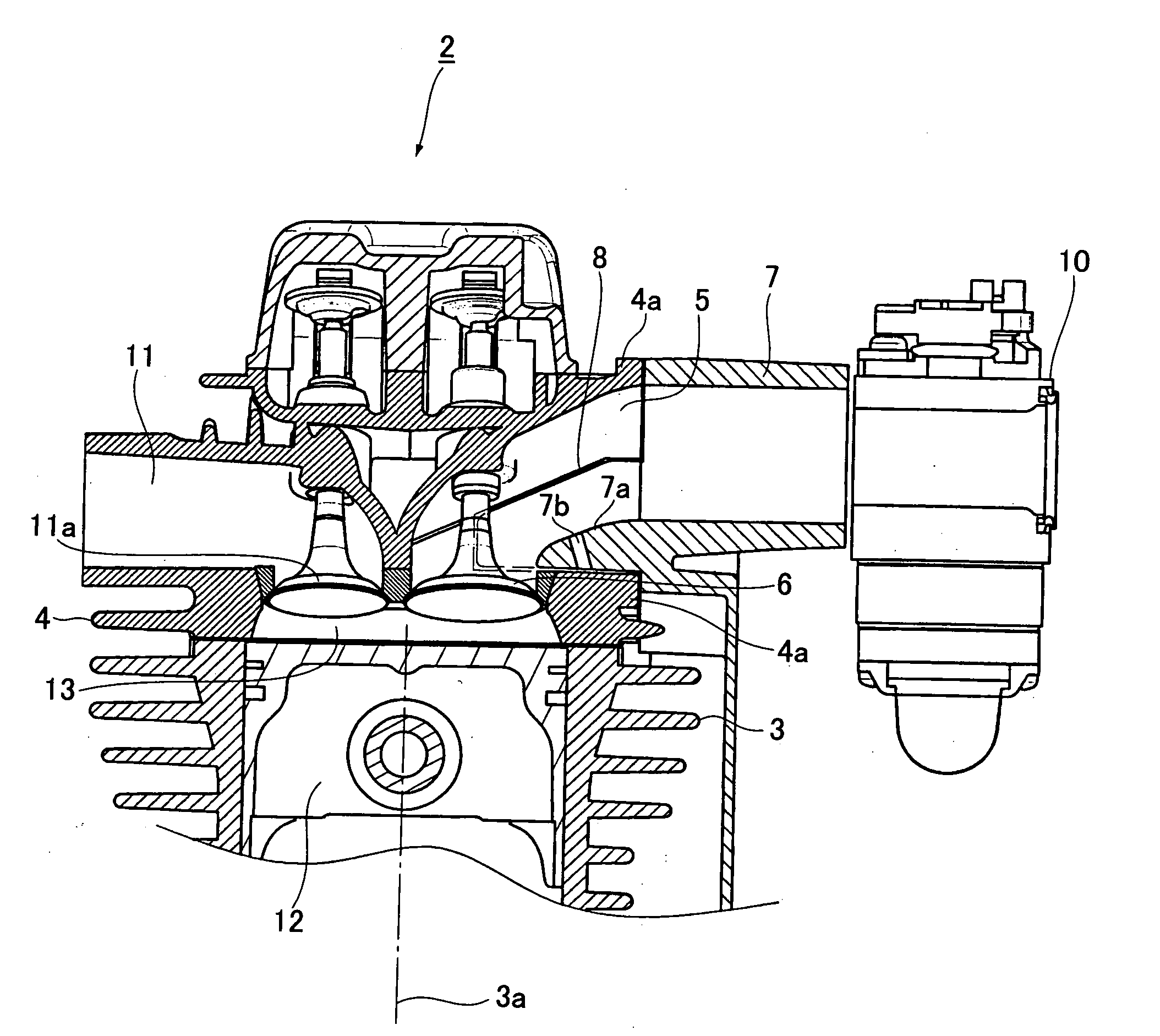
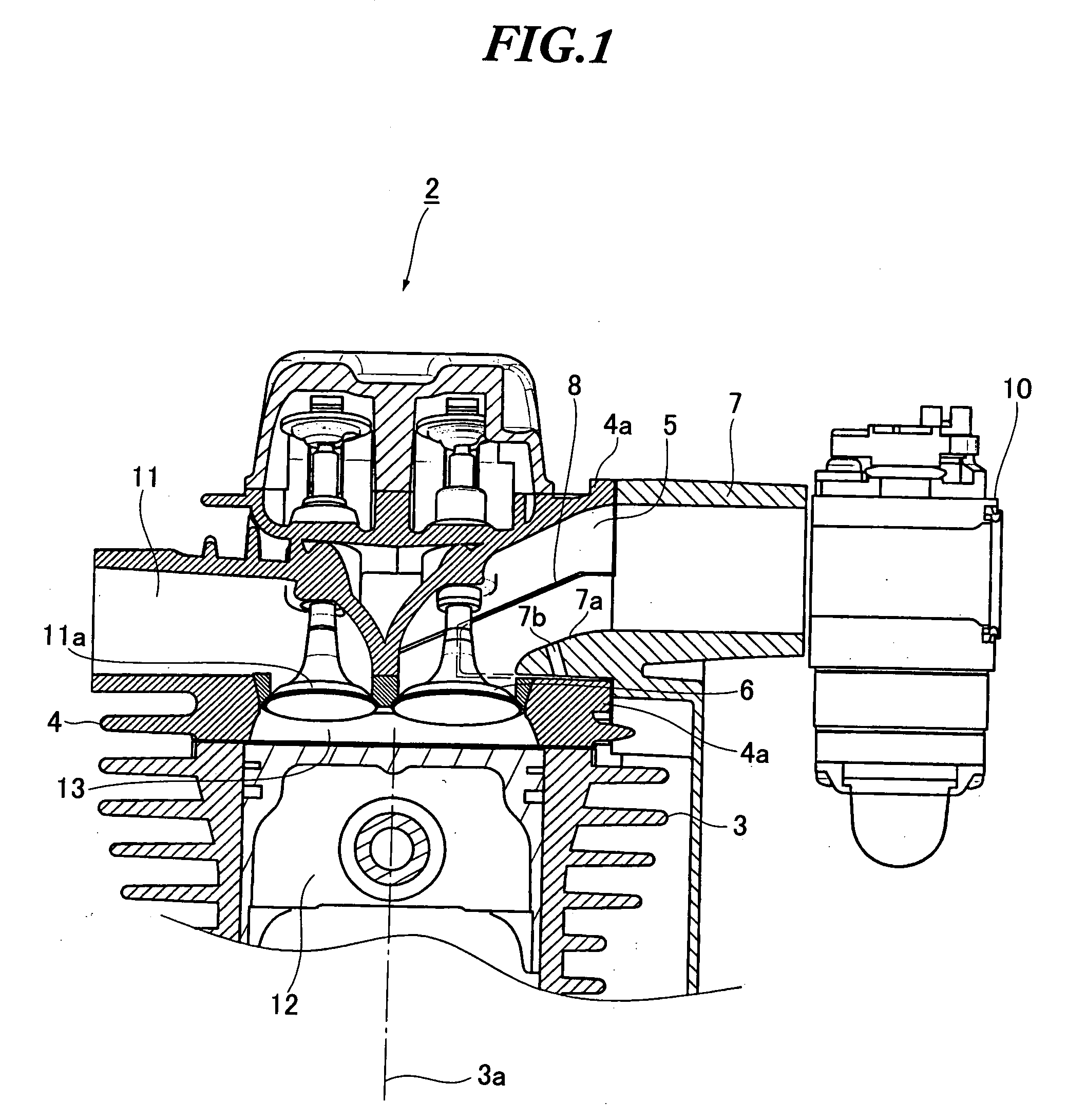
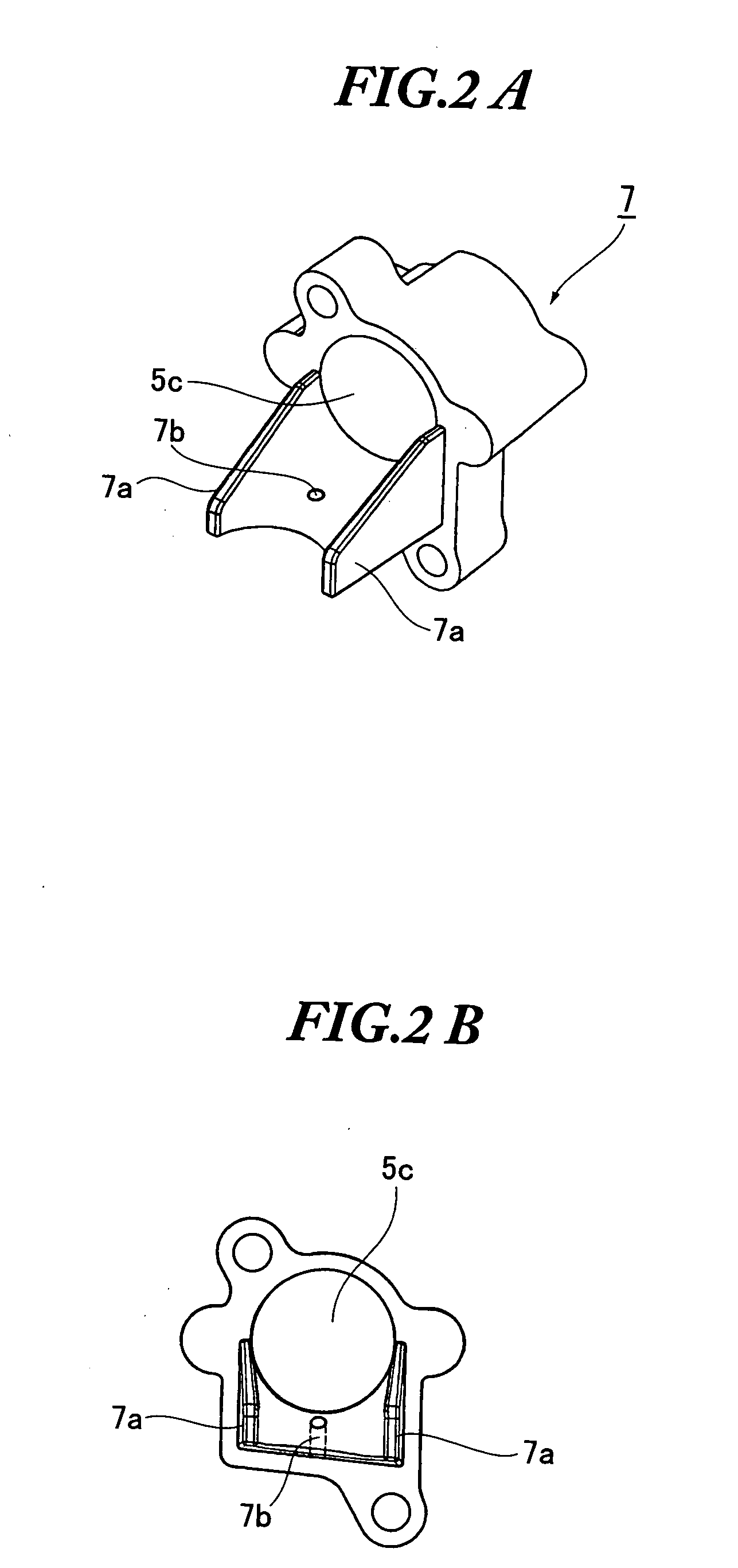
[0030]One preferred embodiment of the 4-cycle engine of the present invention will be hereinafter described with reference to the drawings. FIG. 1 is a cross sectional view illustrating relevant parts of the 4-cycle engine according to one embodiment of the present invention; FIG. 2A is a perspective view and FIG. 2B is a front view of a heat insulator used in the embodiment of the invention; FIG. 3 is a cross sectional view illustrating relevant parts of the cylinder head of the 4-cycle engine in accordance with the embodiment of the present invention; FIG. 4 is a cross sectional view taken along the line A-A of FIG. 3; and FIG. 5 illustrates one example of use of the 4-cycle engine in accordance with the embodiment of the invention.

[0031]As shown in FIG. 1, a cylinder head 4 is placed on a top of a cylinder 3 and firmly tightened to the cylinder 3 with bolts or the like. Both of the cylinder 3 and the cylinder head 4 are aluminum alloy die castings. The 4-cycle engine 2 in accorda...


PUM


Abstract

An intake port for a 4-cycle engine includes an intake port base integrally formed with a cylinder head, and an intake port forming member that forms an intake port together with the intake port base. The area of the cross section of the intake port orthogonal to a centerline of the intake port is substantially uniform from an open intake side thereof toward a combustion chamber. The angle made by the centerline of the intake port and an intake valve shaft is larger than 90° from a viewpoint of the intake valve. Thereby, the 4-cycle engine can output high power with the intake port shape, as formed with above mentioned configuration, that reduces intake resistance and that uses simple design molds. More specifically, the engine can reliably prevent condensed fuel from remaining in the intake port to avoid incomplete combustion of gas.

Description

BACKGROUND OF THE INVENTION[0001]The present invention relates to a small 4-cycle engine used for driving a portable machine or the like, and more particularly to an intake port thereof.[0002]The present application claims priority from Japanese Patent Application No. 2006-012875, the disclosure of which is incorporated herein by reference.[0003]Small 4-cycle engines used for driving portable machines such as handheld blowers usually have their intake port integrally formed with the cylinder head because of the priority given to reduction of size and weight of the machine including the engine. Also, the cylinder head needs to be designed so that it is easily molded without using complex shape molds for lower cost.[0004]More specifically, the intake port is conventionally designed to be formed so that its centerline on the entrance side is vertical to the centerline of the cylinder, while the centerline on the exit side is parallel to the cylinder centerline, i.e., the centerlines of...

Claims


Application Information

Patent Timeline
IPC IPC(8): F02N3/00
CPCF02F1/425
Inventor SUGIYAMA, MASAKI
Owner MAKITA NUMAZU CORP
Why Eureka
Try Eureka