Stall controller and triggering condition control features for a wind turbine

a technology of stall controller and triggering condition, which is applied in the direction of variable speed operation control, electric generator control, dynamo-electric converter control, etc., can solve the problems of increasing complexity and cost of such devices and systems, increasing noise, and increasing complexity of devices, so as to reduce noise, cost, or reliability problems, and improve torque.

Inactive Publication Date: 2007-07-26
WIND RESOURCE LLC
View PDF23 Cites 45 Cited by
  • Summary
  • Abstract
  • Description
  • Claims
  • Application Information

AI Technical Summary

Benefits of technology

[0009]The control features for a wind turbine of the present invention permit control of the turbine in a full range of wind speeds, as well as to slow or stop turbine rotation in triggered conditions, including conditions in which multipole failures occur in the wind turbine's toque generation generator/alternator and electronic controls therefore, without the noise, cost, or reliability issues associated with furling, pitch regulation, or aeroelastic twist regulation, for example, of the prior art. These control features of the present invention are accomplished via control electronics, which adjust the torque produced by the alternator or other electrical output generation device having a plurality of windings. During normal wind conditions, torque is adjusted for optimum aerodynamic performance and/or maximum output of the wind turbine. In winds above a selected power, the control circuit regulates torque to lower aerodynamic perfo...

Problems solved by technology

Problems with these existing turbines include, but are not limited to, the need to control power, especially in low and high wind conditions, and to provide features to address regulatory and other requirements and needs for stopping or slowing turbine blade rotation under certain triggering conditions, such as in the event of high winds combined with control system failure and/or fa...

Method used


Image

  • Stall controller and triggering condition control features for a wind turbine
  • Stall controller and triggering condition control features for a wind turbine
  • Stall controller and triggering condition control features for a wind turbine

Examples


Embodiment Construction

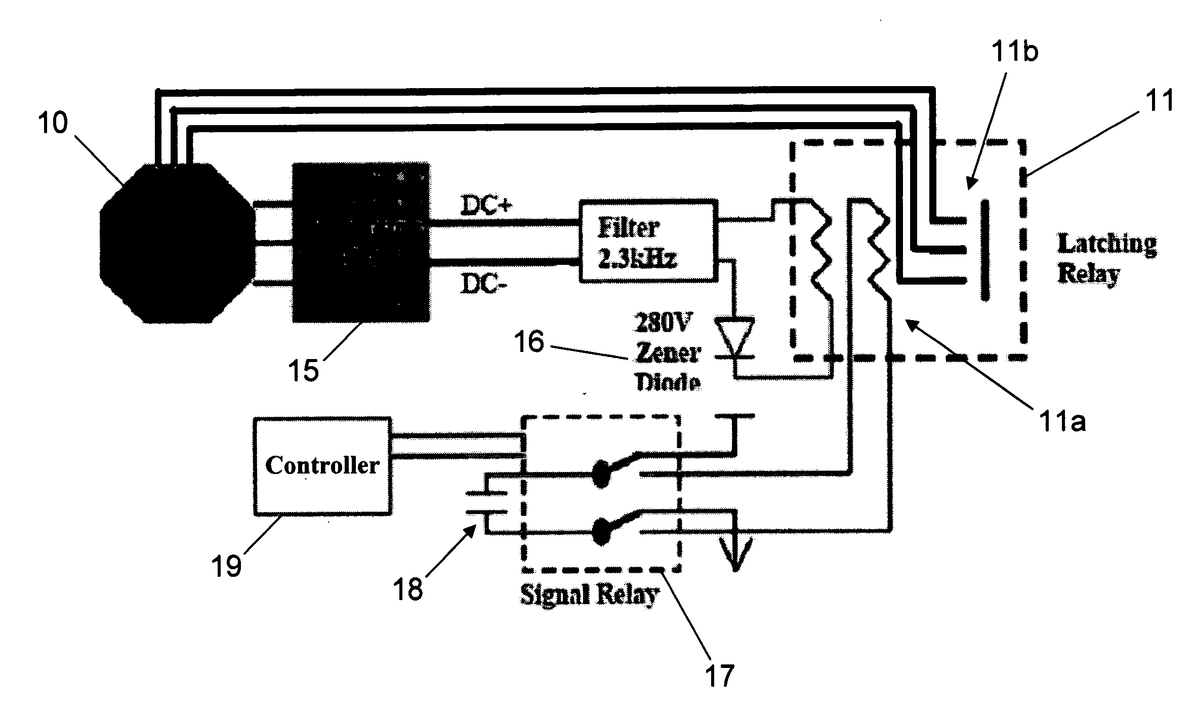
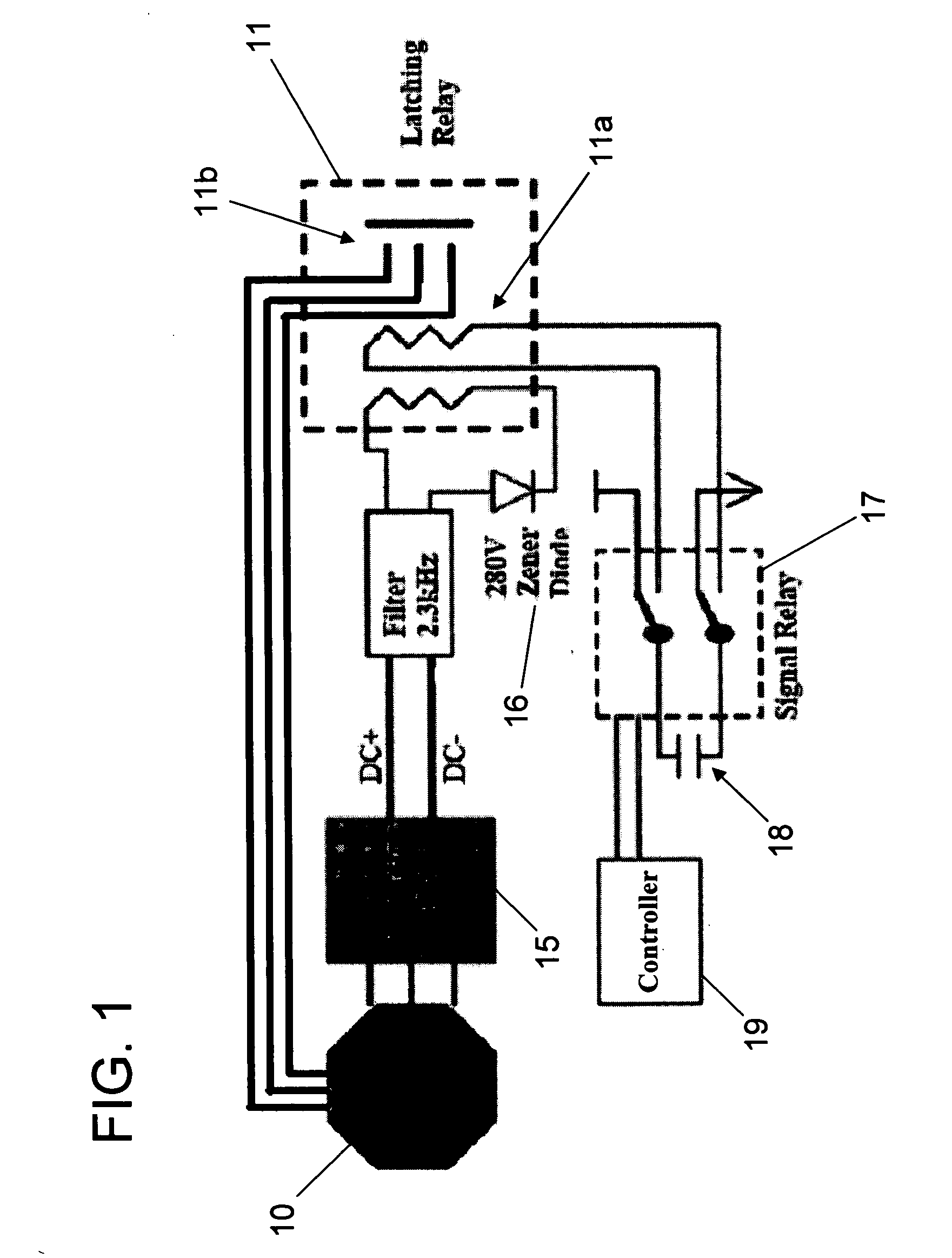
[0022]The wind turbine controller of the present invention, portions of an exemplary variation of which are shown in FIG. 1, includes an electrical output generation device 10, such as an alternator or a generator, and associated circuitry that provides backup control and triggering event control features for the blades of the wind turbine. The device 10 may also include circuitry for normal operational control (not shown in FIG. 1; see e.g., FIG. 6). The exemplary circuit includes an alternating to direct current (AC to DC) converter, such as a rectifying bridge, a DC to DC converter, and a DC to AC converter. In addition, as shown in FIG. 1, the controller includes triggering event control features, such as a winding shorting device 11, (e.g., a latching relay), that provides shorting of the alternator windings to retard wind turbine motion upon triggering events occurring, such as emergencies. Such winding shorting device 11 may operate, for example, in the condition of extremely...


PUM


Abstract

Control features for a wind turbine that control the turbine over a range of wind speeds and under triggering conditions with reduced noise, cost, and reliability issues associated with other such controls. Control is accomplished via control electronics, which adjust the torque produced by the electrical output generation device (e.g., alternator) within the wind turbine. During normal operation, torque is adjusted for optimum aerodynamic performance and maximum output of power. In winds above rated power, the control circuit regulates torque to lower aerodynamic performance, as necessary to maintain desired power level output. In triggering conditions, such as during simultaneous control circuit failure and loss of some portion of the electrical output generation device in extreme winds, wind turbine control is accomplished by increasing torque (e.g., via a separate controller) from the electrical output generation device via shorting of windings, so as to cause retardation of blade rotation.

Description

[0001]This application claims priority to applicant's copending U.S. Provisional Patent Application Ser. No. 60 / 760,407 titled “STALL CONTROLLER AND BACKUP FOR A WIND TURBINE” filed Jan. 20, 2006, the entirety of which is incorporated herein by reference.BACKGROUND OF THE INVENTION[0002]1. Field of the Invention[0003]The present invention relates generally to stall controlling features for a wind turbine that is capable of varying torque via an alternator to cause or induce aerodynamic stall in coupled wind turbine blades. In particular, the wind turbine controller of the present invention includes stall controlling features that enable generation of stall torque under both normal conditions and upon certain triggering conditions occurring, so that in the event of a failure in the windings of the alternator or connectors thereto, or to the controller, sufficient torque remains available in the alternator to control the wind turbine.[0004]2. Background of the Related Art[0005]It is k...

Claims


Application Information

Patent Timeline
IPC IPC(8): H02P9/04
CPCF03D7/0256F03D7/0272F03D7/042F05B2270/1016H02P3/22H02P3/24H02P2101/45H02P9/08H02P25/18Y02E10/721Y02E10/723H02P2101/15H02P9/04Y02E10/72
Inventor CALLEY, DAVID GREGORY
Owner WIND RESOURCE LLC
Why Eureka
Try Eureka