Rotation sensor, and method for outputting signals from rotation sensor
a technology of rotation sensor and signal output, which is applied in the field of rotation sensor, can solve the problems of difficult to obtain a stable information transmission speed, one of the foregoing cannot be constantly monitored,
- Summary
- Abstract
- Description
- Claims
- Application Information
AI Technical Summary
Benefits of technology
Problems solved by technology
Method used
Image
Examples
first embodiment
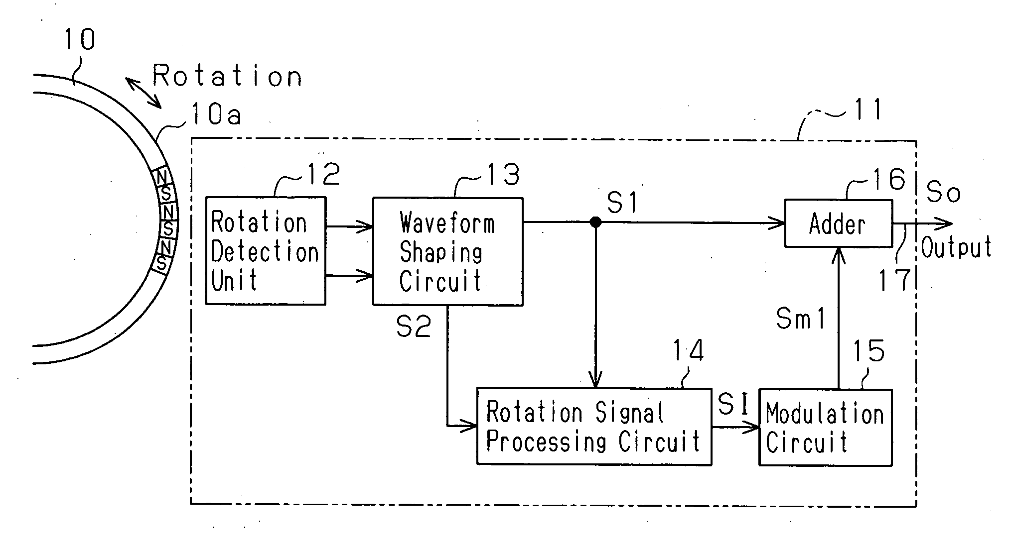
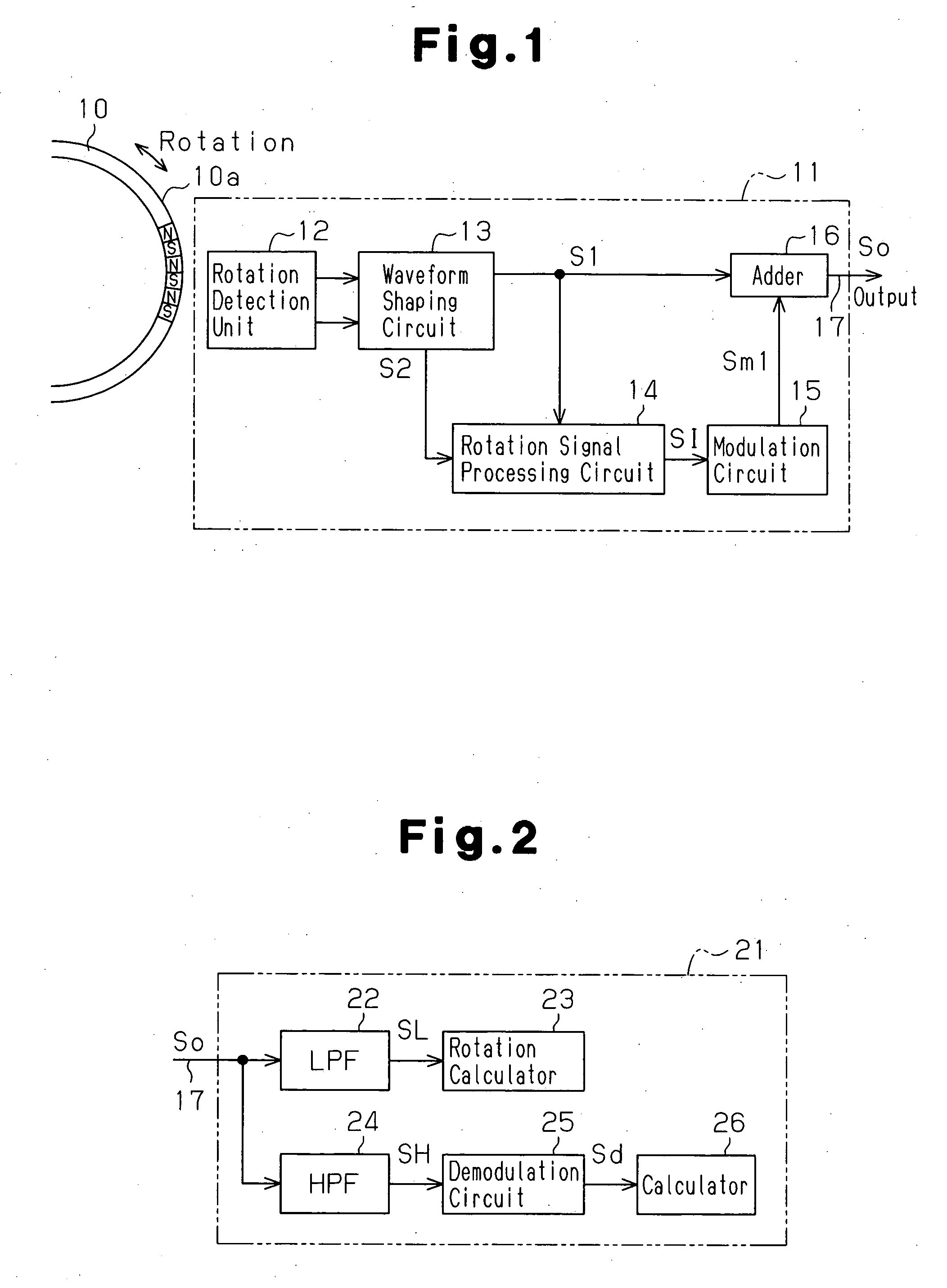
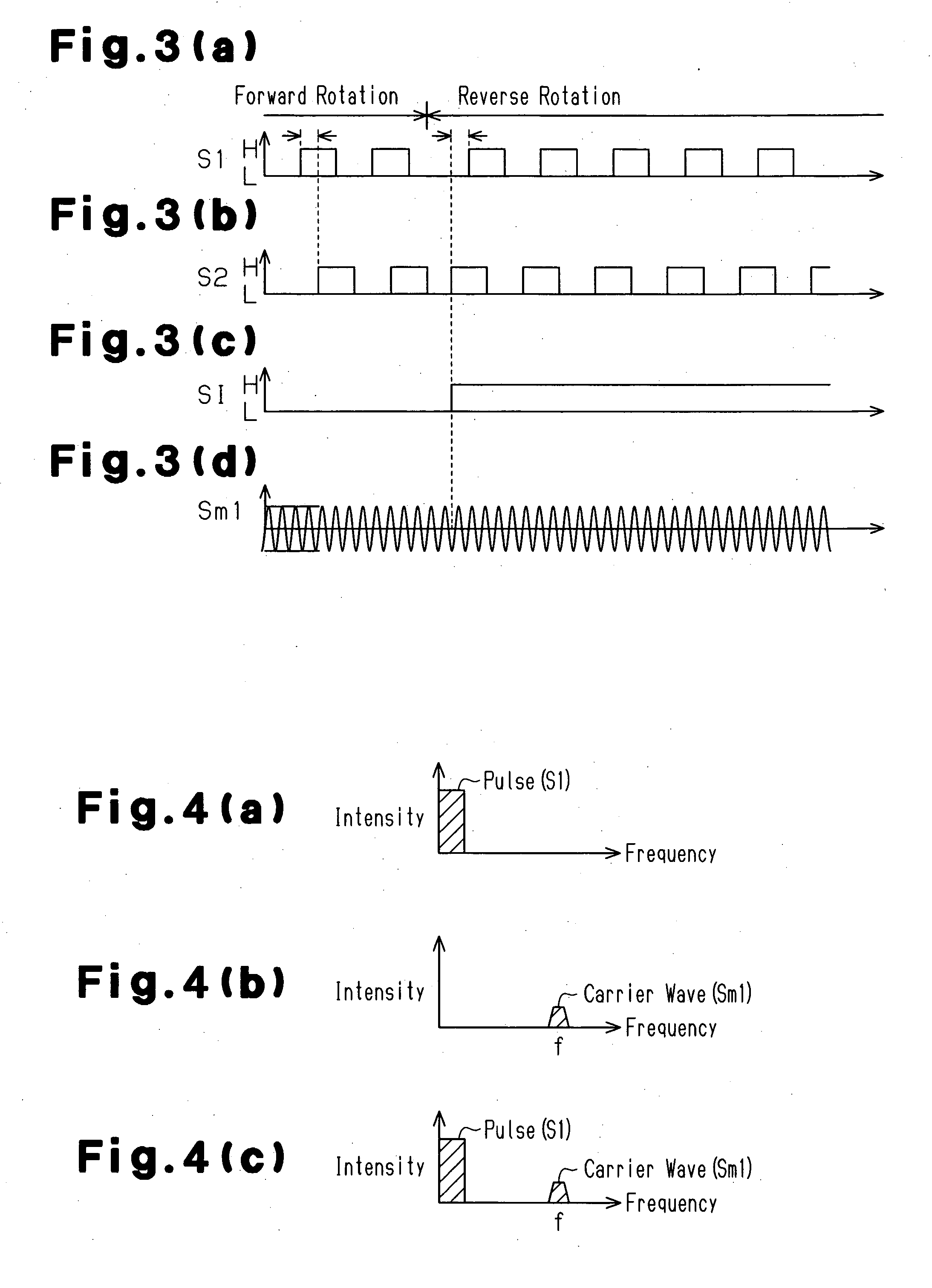
[0025] A rotation sensor according to the present invention for detecting the rotation speed and rotation direction of a wheel for an automobile or the like will now be discussed with reference to FIGS. 1 to 4(d). FIG. 1 is a block diagram of a rotation sensor 11 for detecting rotation of a rotor 10, which is a detection subject. FIG. 2 is a block diagram of a controller 21 that receives a signal from the rotation sensor 11 via a wire (connection wire). FIGS. 3(a) to 3(d) are time charts for output signals generated by various types of circuits incorporated in the rotation sensor 11. FIGS. 4(a) to 4(c) are schematic diagrams showing the relationship between the frequency and intensity of these output signals.
[0026] As shown in FIG. 1, the rotor 10 has a peripheral portion defining a magnetic portion 10a in which N poles and S poles switch every predetermined angle. The rotor 10 rotates integrally with the wheel. The rotation sensor 11 is arranged facing towards the magnetic portion ...
third embodiment
[0066] The adder 16 superimposes the pulse signal S1 from the waveform shaping circuit 13 with the modulated wave Sm4 and sends the output signal So to the output wire 17. Since this is performed in the same manner as in the third embodiment, this will not be described in detail.
[0067] The output signal So output via the output wire 17 is processed by a controller corresponding to the controller of the third embodiment. The controller of the present embodiment extracts the desired information (information signals SI, SI3, and SI4) by dividing the information signal Sd (refer to FIG. 2), which passes through the HPF 24 to be demodulated by the demodulation circuit 25, in accordance with a predetermined standard. As a result, the calculator 26 of the controller acquires rotation direction information of the rotor 10 and external information.
[0068] As described above, in addition to the advantages of the third embodiment, the present embodiment has the advantage described below.
[0069...
second embodiment
[0075] The output signal So output via the output wire 17 is processed by a controller corresponding to that of the In lieu of the HPF 24, the controller includes a bandpass filter (BPF), which enables passage of a signal in the high frequency band centered about the frequency f, and a BPF, which enables passage of a signal in the high frequency band centered about the frequency fm. The controller includes a plurality of demodulation circuits 25 for separately demodulating these band passage signals. Thus, the controller acquires the rotation direction of the rotor 10, the external information via the external wire 39, and the external information acquired through wireless communication by the rotation sensor 46.
PUM
 Abstract
Description
Claims
Application Information
 - R&D
- Intellectual Property
- Life Sciences
- Materials
- Tech Scout
- Unparalleled Data Quality
- Higher Quality Content
- 60% Fewer Hallucinations
Browse by: Latest US Patents, China's latest patents, Technical Efficacy Thesaurus, Application Domain, Technology Topic, Popular Technical Reports.
© 2025 PatSnap. All rights reserved.Legal|Privacy policy|Modern Slavery Act Transparency Statement|Sitemap|About US| Contact US: help@patsnap.com


