Dual path acoustic data coupling system and method

a data coupling system and acoustic data technology, applied in transmission systems, generators/motors, instruments, etc., can solve problems such as low-voltage signal transients or noise, improper operation of the overall system, and affecting the overall operation, performance and cost of the coupler

Inactive Publication Date: 2007-07-26
AVAGO TECH INT SALES PTE LTD
View PDF44 Cites 70 Cited by
  • Summary
  • Abstract
  • Description
  • Claims
  • Application Information

AI Technical Summary

Problems solved by technology

One reason such signals must be isolated is because the switching of high voltage signals can cause transients or noise on low voltage signals in the system.
This noise on the low voltage signals, which would typically be digital logic level signals, can result in erroneous processing of the low voltage signals and thereby can result in improper operation of the overall system, as will be understood by those skilled in the art.
The precise manner in which transitions in the input signal are converted into a signal that is applied to the first piezoelectric element affects the overall operation, performance, and cost of the coupler.
Another limitation with existing acoustic data couplers is channel density, meaning the size of existing couplers may be too large to allow the required numbers of couplers to be formed within a maximum specified space.
Magnetically and capacitively isolated data couplers are further limited by susceptibility to external electromagnetic interference signals increasing the noise received in addition to the desired transmitted signal across the magnetic or capacitive isolation barrier.

Method used


Image

  • Dual path acoustic data coupling system and method
  • Dual path acoustic data coupling system and method
  • Dual path acoustic data coupling system and method

Examples


Embodiment Construction

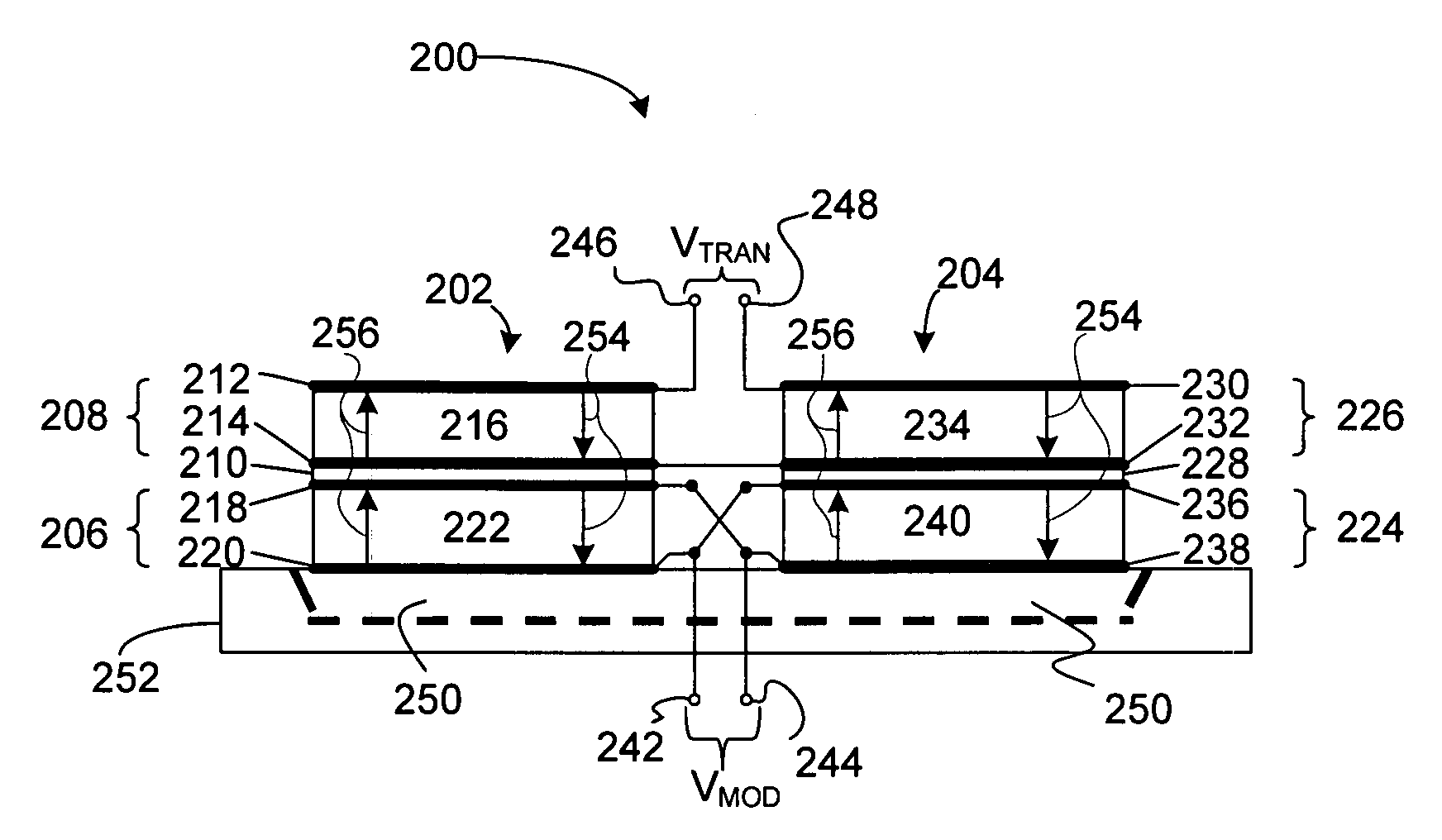
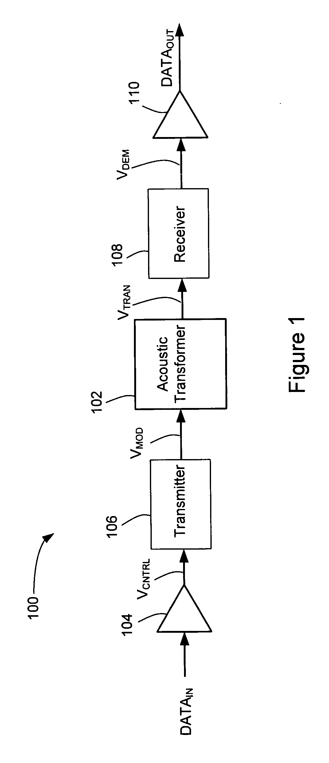
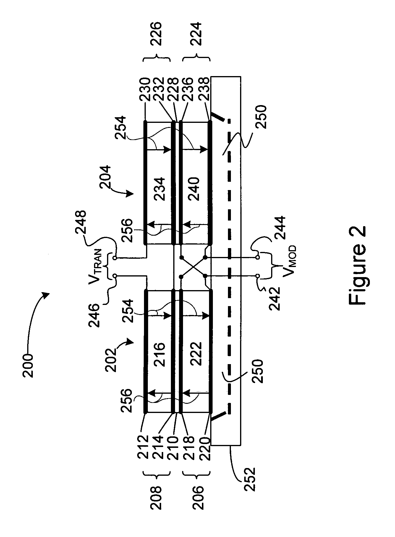
[0018]FIG. 1 is a functional block diagram of an acoustic data coupler 100 including an acoustic isolation transformer 102 according to one embodiment of the present invention. In operation, a digital data input signal DATAIN is applied through an input buffer 104 to generate an input control signal VCNTRL, which is applied to a transmitter 106. In response to the input control signal VCNTRL from the input buffer 104, the transmitter 106 generates a modulated signal VMOD, which may be a continuous periodic signal, burst periodic signal, or burst nonperiodic signal, as will be discussed in more detail below. In response to the modulated signal VMOD, the acoustic isolation transformer 102 generates a transformer output signal VTRAN that is utilized in generating a data output signal DATAOUT from the data coupler 100. The way in which the transmitter 106 converts or modulates the DATAIN signal to generate the modulated signal VMOD that is applied to the acoustic isolation transformer 1...


PUM


Abstract

A data coupler includes first and second acoustic isolation transformers that develop first and second isolated output signals in response to first and second modulated input signals. A first and a second transmitter is coupled to the first and second acoustic isolation transformers to receive a first and a second data input signal and generate the first and second modulated input signal in response to the first and second data input signals. A first and a second receiver is coupled to the first and second acoustic isolation transformers to receive the first and a second isolated output signals and generate first and second demodulated signals responsive to the first and second isolated output signals. An output decision circuit is coupled to the first and second receivers to receive the first and second data output signals and generates a data output signal responsive to the first and second demodulated signals.

Description

BACKGROUND OF THE INVENTION [0001] Many electronic systems have a need to isolate electrical signals in one portion of the system from electrical signals in another portion of the system. In many control systems, for example, both high voltage and low voltage signals may be generated and monitored, and isolation between the signals is required for proper operation of the system. One reason such signals must be isolated is because the switching of high voltage signals can cause transients or noise on low voltage signals in the system. This noise on the low voltage signals, which would typically be digital logic level signals, can result in erroneous processing of the low voltage signals and thereby can result in improper operation of the overall system, as will be understood by those skilled in the art. Another reason for isolating signals may be safety, such as in medical systems where high higher voltages in portions of the system must be isolated from other portions that come into...

Claims


Application Information

Patent Timeline
Patent Type & Authority Applications(United States)
IPC IPC(8): H03H9/54
CPCG08C23/02H01L2224/48091H01L2224/48137H01L2224/48227H01L2924/01078H01L2924/15311H03H9/60H01L2924/19041H03H9/584H03H9/587H01L2924/00014
Inventor UNKRICH, MARK A.
Owner AVAGO TECH INT SALES PTE LTD
Why Eureka
Try Eureka