
Optical amplification module and laser light source including the same

a technology of optical amplification and laser light source, which is applied in the direction of lasers, electromagnetic transmission, transmission, etc., can solve the problems of increasing the loss of optical fiber itself, and achieve the effect of reducing the concentration of rare earth elements, and still more effectively suppressing photodarkening

Inactive Publication Date: 2007-07-26
MEGAOPTO
View PDF7 Cites 6 Cited by
  • Summary
  • Abstract
  • Description
  • Claims
  • Application Information

AI Technical Summary

Benefits of technology

[0008] Namely, in a conventional laser light source, high power light is generated within an optical fiber. The generation of high power light damages the dopants and impurities in the optical fiber, and this leads to increasing loss of the optical fiber itself. This phenomenon is called photodarkening, and is due to the fact that the rare earth element, in the optical amplification medium which have a high population inversion, is damaged by the high power light. With a fiber having a high rare earth doping concentration, photodarkening tends to occur relatively easily.
[0009] In order to overcome the above-mentioned problems, it is an object of the present invention to provide an optical amplification module having a suitable construction for effectively suppressing photodarkening, and a laser light source including the same.
[0012] In the optical amplification module having the aforesaid construction, the first pumping light outputted from the first pumping light source first propagates through the first optical amplification medium, and then through the second optical amplification medium. The incident light is amplified in the first optical amplification medium, and a first amplified light is emitted from the first optical amplification medium. This first amplified light is further amplified in the second optical amplification medium, and a second amplified light is emitted from the second optical amplification medium. In the first optical amplification medium into which the first pumping light is introduced, although the power of the first pumping light is relatively high, the rare earth element concentration is relatively low. However, in the second optical amplification medium through which the first pumping light subsequently propagates, although the rare earth element concentration is relatively high, the power of the first pumping light becomes relatively low. This construction makes it possible to increase the population inversion of the first optical amplification medium with a low rare earth element concentration, while at the same time suppressing the population inversion of the second optical amplification medium with a high rare earth element concentration. Therefore, in both the first optical amplification medium and second optical amplification medium, a high amplification gain can be obtained while photodarkening is suppressed.
[0013] In the optical amplification module according to the present invention, the population inversion in the first optical amplification medium is preferably 40% or more, and the rare earth element concentration in the first optical amplification medium is preferably not greater than half of the rare earth element concentration in the second optical amplification medium. The unsaturated absorption of the first optical amplification medium is preferably not less than 60% of the unsaturated absorption of the second optical amplification medium. The population inversion at the light entrance end of the second optical amplification medium is preferably less than 40%. Also, in the optical waveguide region of each of the first and second optical amplification media, in order to reduce the rare earth element concentration, a trivalent cation other than a rare earth element is preferably contained. In these cases, photodarkening can be still more effectively suppressed.

Problems solved by technology

The inventors have studied conventional laser light sources in detail, and as a result, have found problems as follows.
The generation of high power light damages the dopants and impurities in the optical fiber, and this leads to increasing loss of the optical fiber itself.
This phenomenon is called photodarkening, and is due to the fact that the rare earth element, in the optical amplification medium which have a high population inversion, is damaged by the high power light.

Method used


Image

  • Optical amplification module and laser light source including the same
  • Optical amplification module and laser light source including the same
  • Optical amplification module and laser light source including the same

Examples


first embodiment

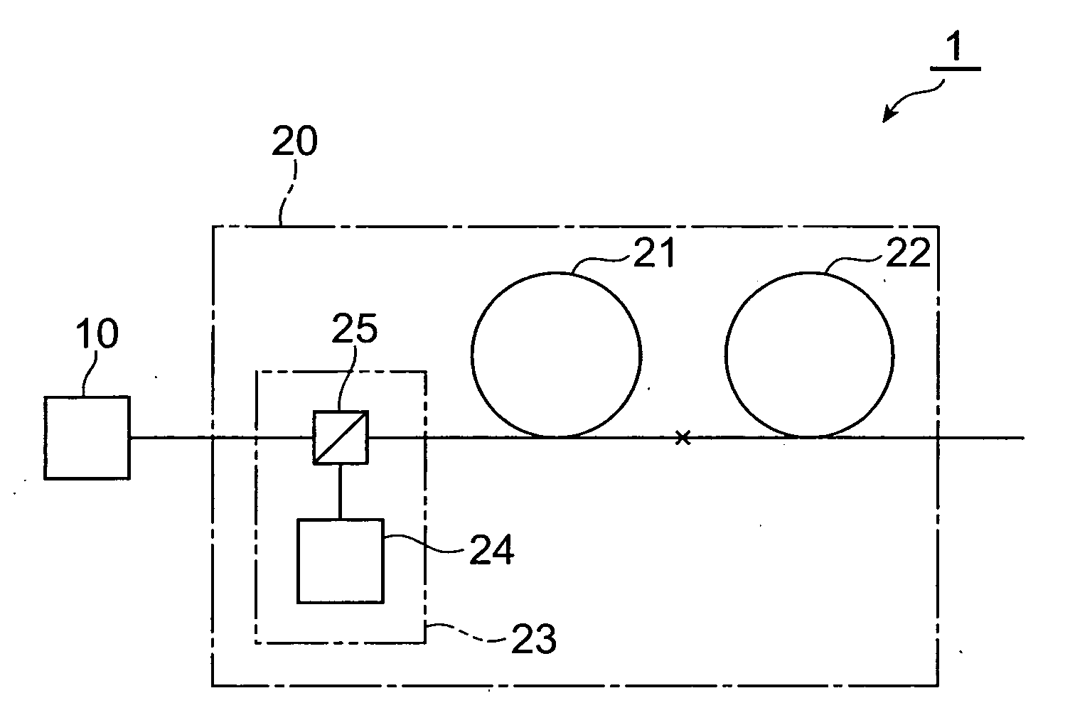
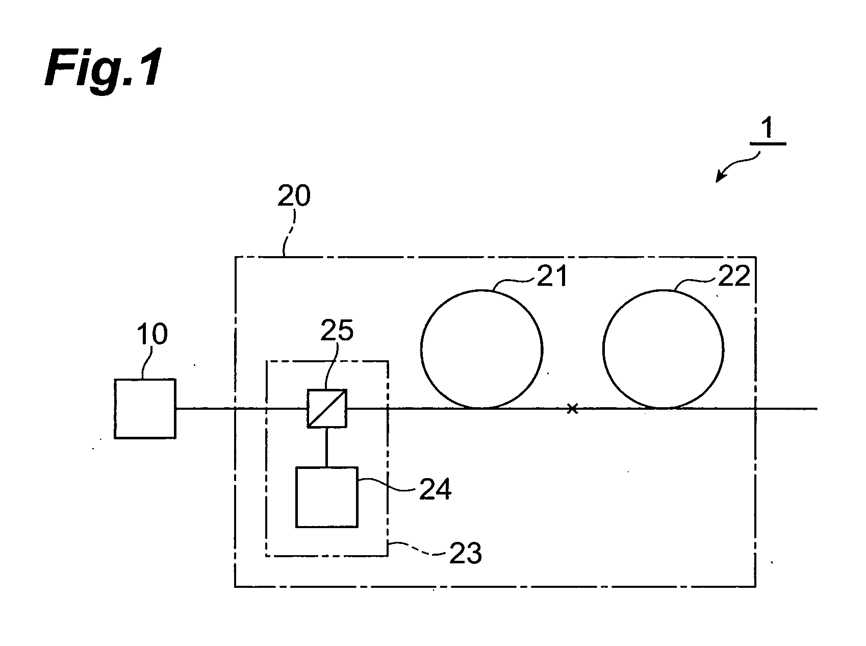
[0034]FIG. 1 is a drawing showing the construction of a first embodiment of a laser light source according to the present invention. A laser light source 1 shown in FIG. 1 comprises a light source 10 and an optical amplification module 20 (optical amplification module according to the present invention). In the laser light source 1, the light from the light source 10 is amplified in the optical amplification module 20, and the obtained amplified light is emitted.

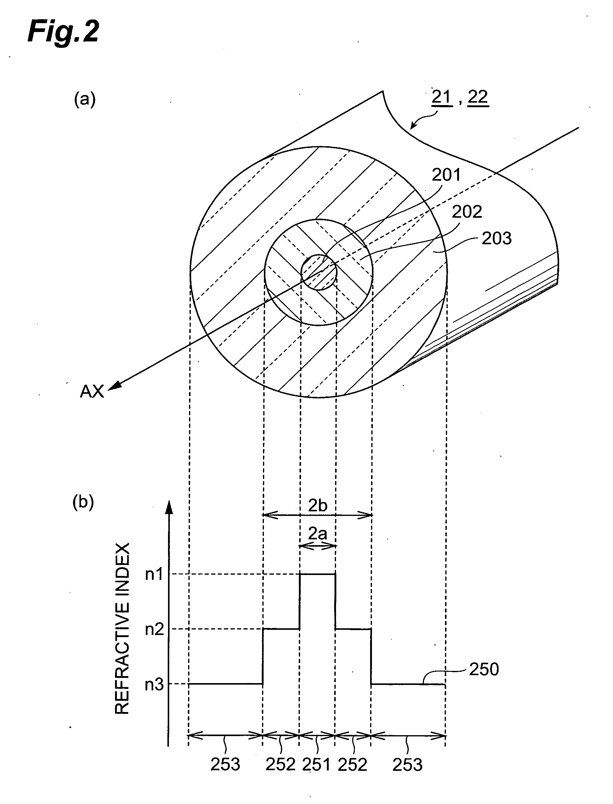
[0035] The optical amplification module 20 comprises a first optical amplification medium 21, a second optical amplification medium 22 and a pumping section 23. Each of the first optical amplification medium 21 and the second optical amplification medium 22 is an optical waveguide whose optical waveguide region is doped with a rare earth element, and is preferably an optical fiber having a core region doped with Yb as a rare earth element. One end of the first optical amplification medium 21 and the second optical amplifica...

second embodiment

[0053]FIG. 9 is a drawing showing a construction of a second embodiment of the laser light source according to the present invention. A laser light source 2 according to the second embodiment shown in this FIG. 9 comprises the light source 10 for outputting light to be amplified, and an optical amplification module 30 (optical amplification module according to the present invention). In the laser light source 2, the light to be amplified from the light source 10 is amplified in the optical amplification module 30, and the obtained amplified light is outputted.

[0054] The optical amplification module 30 may comprise two or more optical amplification units, each comprising a pumping light source, an optical multiplexer and an optical amplification medium. In the laser light source 2 according to the second embodiment, the optical amplification module 30 comprises a first optical amplification unit 30A, a second optical amplification unit 30B and a third optical amplification unit 30C....


PUM


Abstract

The present invention relates to an optical amplification module having a construction which effectively suppresses photodarkening, and to a laser light source including the same. The laser light source comprises a light source for outputting light to be amplified, and an optical amplification module. The optical amplification module comprises two types of optical amplification media having different rare earth element concentrations, and a pumping light source. The low concentration medium and the high concentration medium are disposed in the propagation direction of pumping light such that the population inversion of the low concentration medium is higher than that of the high concentration medium. Hence, by arranging two types of optical amplification media with different rare earth concentrations such that the population inversion of the low concentration medium is higher than that of the high concentration medium, sufficient overall gain of the laser light source can be obtained while effectively suppressing photodarkening in the two types of optical amplification media.

Description

CROSS-REFERENCE TO RELATED APPLICATION [0001] This application claims priority to Provisional Application Ser. No. 60 / 780,074 filed on Mar. 8, 2006 by the same Applicant, which is hereby incorporated by reference in its entirety.BACKGROUND OF THE INVENTION [0002] 1. Field of the Invention [0003] The present invention relates to an optical amplification module which amplifies light in an optical amplification medium, and to a laser light source including the optical amplification module. [0004] 2. Related Background Art [0005] At present, processing technology using laser beams is attracting much attention, and demand for laser light sources is increasing in various fields such as machining and medical treatment. In particular, among these laser light sources, a fiber laser light source has been attracting special attention. This fiber laser source comprises an optical fiber which is doped with various rare earth elements such as Yb, Er and Tm as an optical amplification medium, and ...

Claims


Application Information

Patent Timeline
Patent Type & Authority Applications(United States)
IPC IPC(8): H01S3/00H04B10/12
CPCH01S3/06716H01S3/094007H01S3/094003H01S3/06758
Inventor TAMAOKI, SHINOBUKAKUI, MOTOKI
Owner MEGAOPTO
Learn More