Cooled mirror dew-point hygrometer

a technology of dew-point hygrometer and mirror, which is applied in the direction of instruments, material moisture content, thermal analysis of materials, etc., can solve the problem of taking a long time to measure the dew-point temperature, and achieve the effect of shortening the waiting time and quick increasing the surface temperature of the mirror

Inactive Publication Date: 2007-07-26
YAMATAKE HONEYWELL CO LTD
View PDF17 Cites 12 Cited by
  • Summary
  • Abstract
  • Description
  • Claims
  • Application Information

AI Technical Summary

Benefits of technology

[0014] The present invention has been made to solve the conventional problem described above, and has as its object to provide a cooled mirror dew-point hygrometer capable of quickly increasing a mirror surface temperature and greatly shortening the waiting time until the measurement of a dew-point temperature when the dew point of a measurement target gas abruptly increases during the measurement.

Problems solved by technology

Therefore, it takes a long time until the measurement of the dew-point temperature is allowed.

Method used


Image

  • Cooled mirror dew-point hygrometer
  • Cooled mirror dew-point hygrometer
  • Cooled mirror dew-point hygrometer

Examples


first embodiment

Detection Scheme

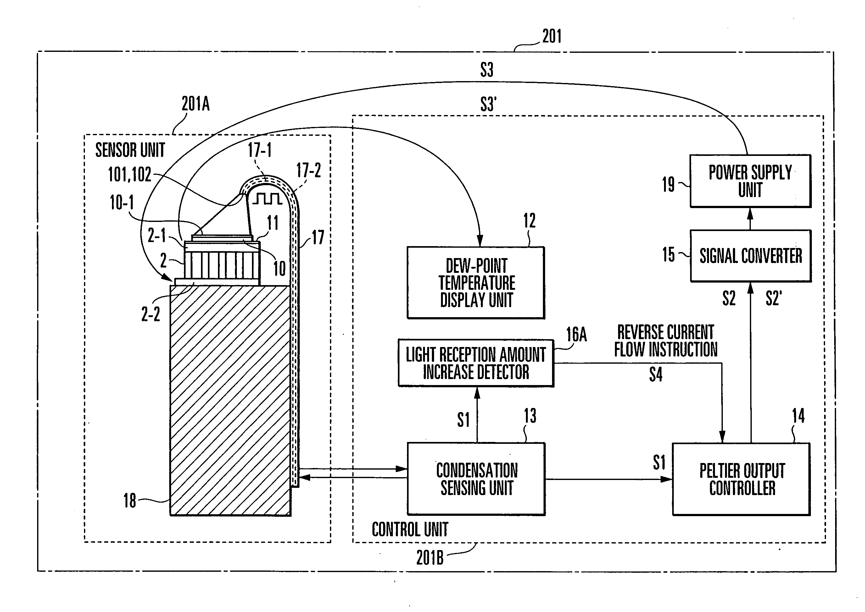
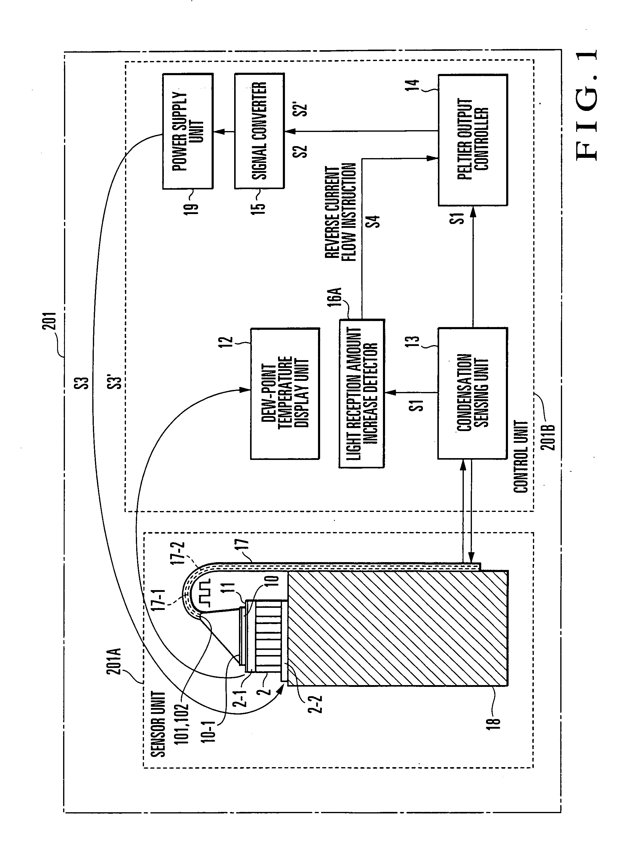
[0031]FIG. 1 shows the schematic arrangement of a cooled mirror dew-point hygrometer according to the first embodiment of the present invention. A cooled mirror dew-point hygrometer 201 comprises a sensor unit 201A and control unit 201B.

[0032] A mirror 10 is mounted on a cooling surface 2-1 of a thermoelectric cooling element (Peltier element) 2. The mirror 10 is obtained by mirror-finishing a surface 10-1 of a silicon chip. A platinum thin-film temperature measurement resistor (temperature detection element) 11 is formed at the bonding surface between the mirror 10 and the cooling surface 2-1 of the thermoelectric cooling element 2. A columnar heat sink 18 is attached to a heating surface 2-2 of the thermoelectric cooling element 2. A stainless steel tube 17 having a J-shaped upper end portion is disposed along the heat sink 18.

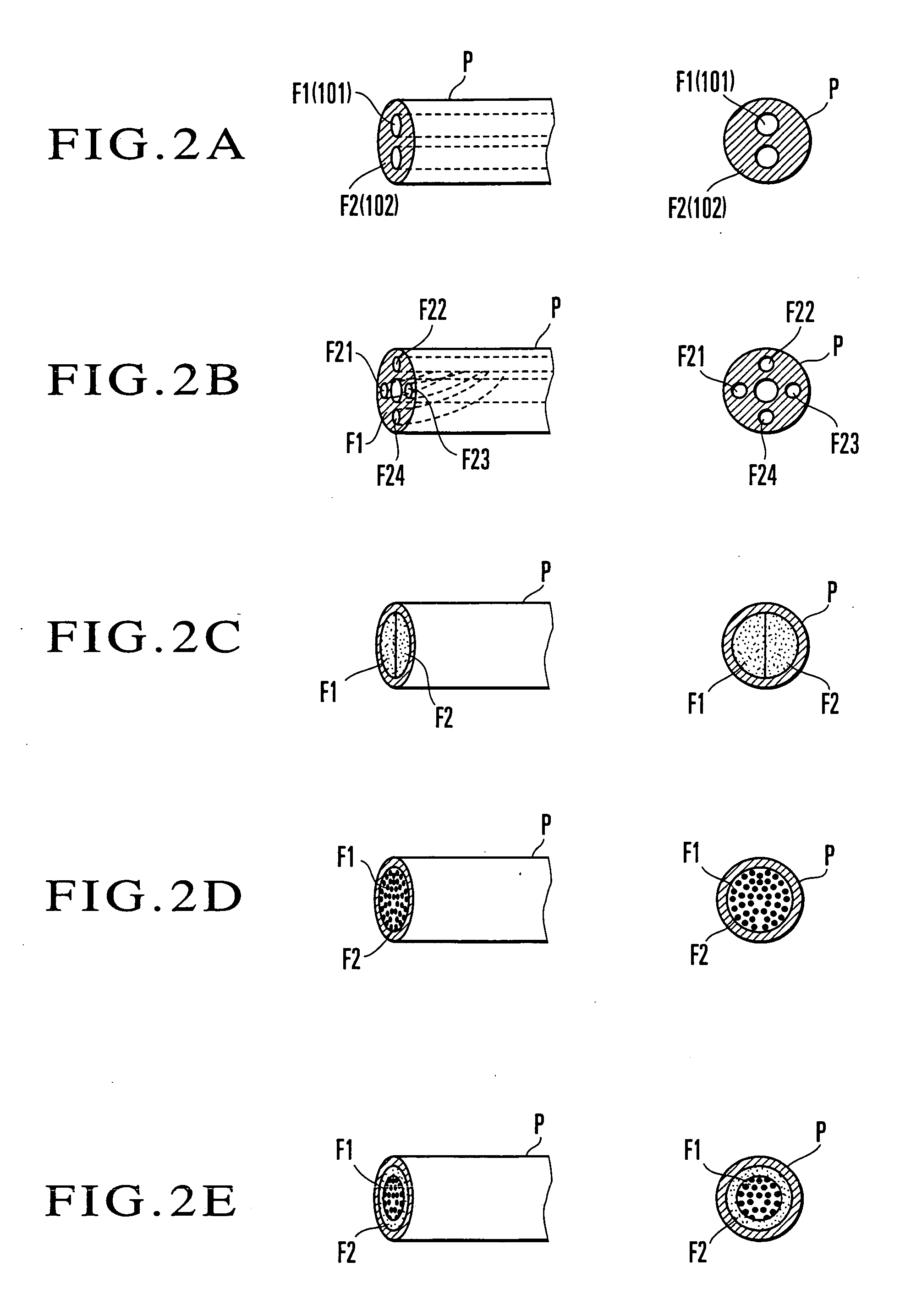
[0033] Various types of tubes P accommodating optical fibers shown in FIGS. 2A to 2E can be used as the tube 17. As shown in FIG. 2A, in t...

second embodiment

ed Light Detection Scheme

[0058]FIG. 8 shows the schematic arrangement of a cooled mirror dew-point hygrometer according to the second embodiment of the present invention. In a cooled mirror dew-point hygrometer 202, an optical fiber 17-1 on the light-emitting side and an optical fiber 17-2 on the light-receiving side are arranged not in the same direction, but symmetrically interposing a mirror 10 between the fibers 17-1 and 17-2. The optical fiber 17-1 on the light-emitting side and the optical fiber 17-2 on the light-receiving side have J-shaped curved portions. Distal end portions 101 and 102 of the curved portions face a mirror surface 10-1 of the mirror 10 and are inclined symmetrically at a predetermined inclination angle with respect to the mirror surface 10-1.

[Measurement of Dew-Point Temperature]

[0059] In the cooled mirror dew-point hygrometer 202, a sensor unit 202A is placed in the measurement target gas.

[0060] A condensation sensor 13 obliquely applies pulse light at ...


PUM

PropertyMeasurementUnit
reverse currentaaaaaaaaaa
temperatureaaaaaaaaaa
thresholdaaaaaaaaaa

Abstract

A cooled mirror dew-point hygrometer includes a thermoelectric cooling element, mirror, light-emitting unit, light-receiving unit, temperature detector, dew-point increase detector, and control unit. The control unit forcibly supplies a current to the thermoelectric cooling element in a direction reverse to a positive direction when the dew-point increase detector detects a rise in dew point.

Description

BACKGROUND OF THE INVENTION [0001] The present invention relates to a cooled mirror dew-point hygrometer for detecting as a dew point a temperature of a mirror surface in an equilibrium state having no increase / decrease in dew condensation in such a manner that the mirror surface exposed to a measurement target gas is cooled using a thermoelectric cooling element such as a Peltier element and part of steam contained in the measurement target gas is condensed on the mirror surface. [0002] A dew-point detection method is conventionally known as a humidity measurement method. In this detection method, the temperature of a measurement target gas is decreased, part of steam contained in this gas is condensed, and the dew condensation temperature is measured to detect the dew point. For example, the following conventional cooled mirror dew-point hygrometer is known. A mirror is cooled using a freezing medium, freezer, or electronic cooler. A change in intensity of light reflected by the s...

Claims


Application Information

Patent Timeline
Patent Type & Authority Applications(United States)
IPC IPC(8): G01N25/02
CPCG01N25/68
Inventor KANAI, YOSHIYUKIIWAKIRI, KENTAKECHI, MASAKIMASUMOTO, SHINGO
Owner YAMATAKE HONEYWELL CO LTD
Why Eureka
Try Eureka