Fuel cell system

a fuel cell and system technology, applied in the field of fuel cell systems, can solve the problems of limited amount of impurity gas that can be eliminated, insufficient hydrogen gas in the fuel space, and gradual increase of impurity gas such as moisture, nitrogen gas, or carbon dioxide in the sealed fuel diffusion space, and achieve the effect of expulsion of impurity gas

Inactive Publication Date: 2007-07-26
CANON KK
View PDF3 Cites 8 Cited by
  • Summary
  • Abstract
  • Description
  • Claims
  • Application Information

AI Technical Summary

Benefits of technology

[0013]It is, therefore, an object of the present invention to provide a fuel cell system that can stably supply hydrogen in a dead-ended fuel cell and can also effectively expel impurity gas that resides / accumulates in a power generation cell even with a small quantity of low-pressure hydrogen gas.

Problems solved by technology

However, when a dead-ended fuel supply is performed, impurity gas such as moisture, nitrogen gas, or carbon dioxide gradually increases in the sealed fuel diffusion space.
According to the passive method of removing impurity gas disclosed in U.S. Pat. No. 6,423,437 above, since impurity gas accumulates in the sealed fuel space, the total amount of impurity gas that can be eliminated is limited.
Further, in a case where a fuel cell is left as it is without supplying fuel while a load is connected to the fuel cell, there is a possibility that the hydrogen gas in the fuel space will be completely consumed and the fuel diffusion layer will be completely filled with impurity gas, and in that case it is also difficult to completely remove the excessive impurity gas.
Further, since provision of a hydrogen gas circulation system itself inhibits size reduction, weight reduction, and cost reduction of the fuel cell system, it is not suitable for a power source of a portable electronic device.
However, unlike the case of a factory, households and the like have no choice other than to utilize a small-capacity fuel tank or a low-pressure forming apparatus, and thus an adequate hydrogen gas pressure or flow rate cannot be secured.
Accordingly, in a conventional purge mechanism configured on the assumption of use of a large volume of hydrogen gas at a high pressure, a sufficient purge effect cannot be achieved.

Method used


Image

  • Fuel cell system
  • Fuel cell system
  • Fuel cell system

Examples


embodiment 1

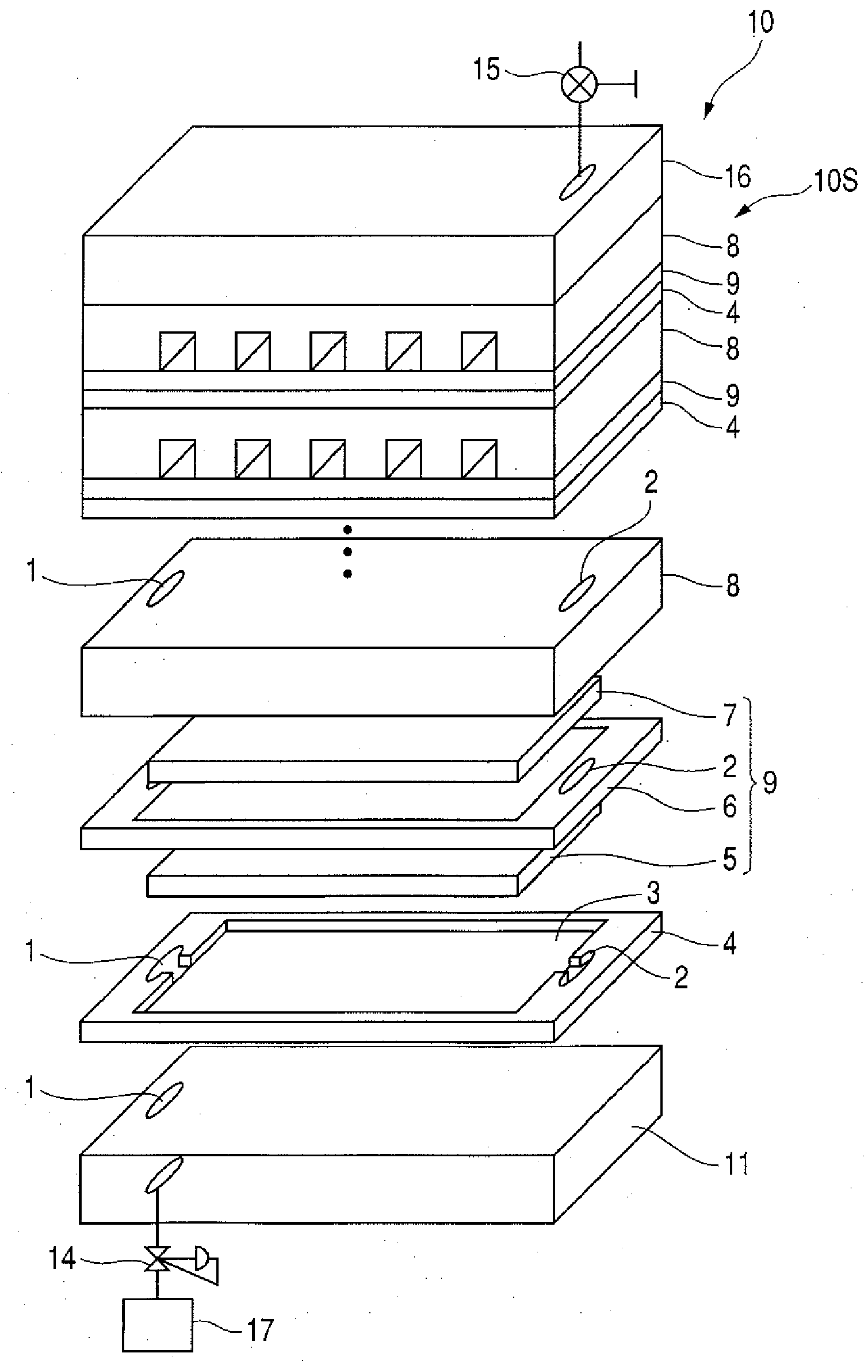
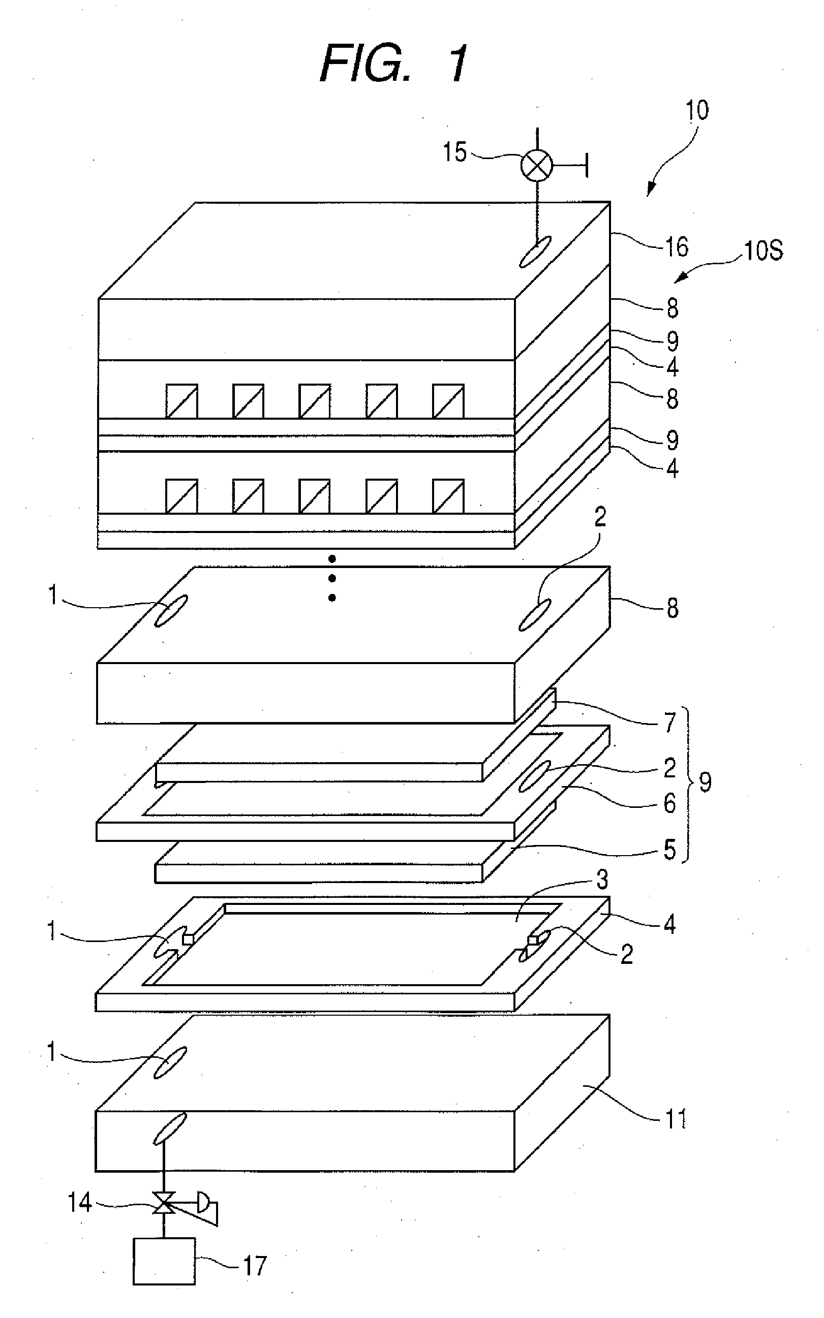
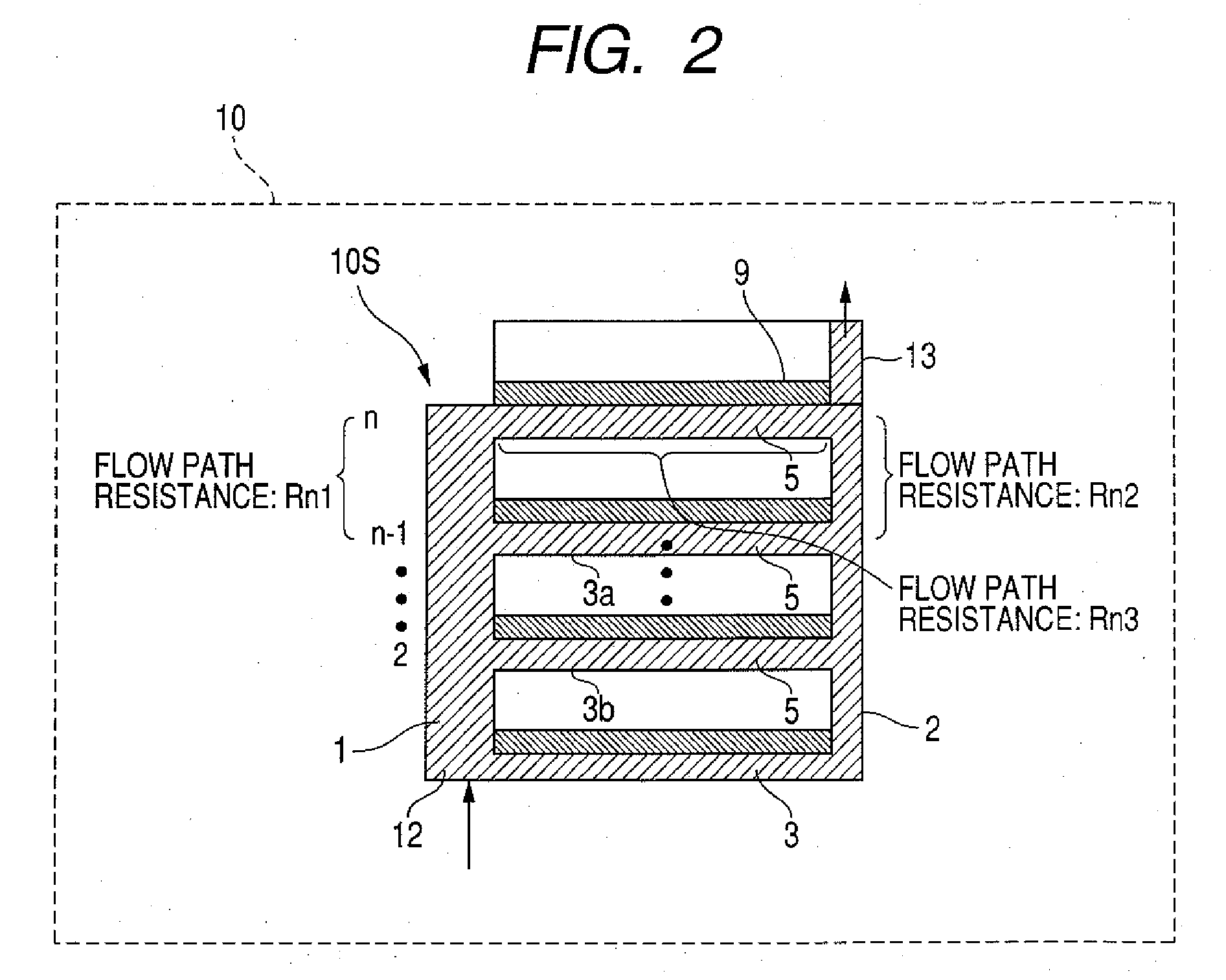
[0041]FIG. 1 is a perspective view illustrating the structure of a fuel cell system according to Embodiment 1; FIG. 2 is a schematic diagram of a flow path of hydrogen gas; FIG. 3 is a diagram illustrating a case in which the discharge of impurity gas is not sufficient; and FIG. 4 is a diagram illustrating water droplet discharge in a branch flow path.

[0042]As shown in FIG. 1, a fuel cell system 10 according to Embodiment 1 comprises a cell stack 10S in which a plurality of power generation cells 9 are stacked and serially connected. The power generation cells 9 are stacked in a state in which they are each interposed between a fuel electrode current connector 4 and an oxidizer electrode current collector 8, and are assembled by restraining all of the components in the stacking direction using pressure plates 11 and 16.

[0043]The power generation cell 9 has a fuel diffusion electrode 5 contacted with one surface of a membrane electrode assembly 6 and an oxygen diffusion electrode 7 c...

embodiment 2

[0072]FIG. 5 is a schematic diagram of a flow path of hydrogen gas in a fuel cell system 20 according to Embodiment 2, and FIG. 6 is a diagram illustrating a case in which the discharge of impurity gas is not sufficient. The fuel cell system 20 according to Embodiment 2 is configured in the same manner as in Embodiment 1 with the exception that the position of the outlet 13 in Embodiment 1 is changed to the same side (lower side) as the inlet 12. Accordingly, the elements which are the same as those shown in FIGS. 1 and 2 are identified by like numerals or symbols, and a detailed description thereof is omitted.

[0073]In the fuel cell system 20 of Embodiment 2, a through hole of the discharge-side main flow path 2 is formed in the pressure plate 11 shown in FIG. 1 to form an outlet 13A as shown in FIG. 5, and the purge valve 15 is connected to the discharge-side main flow path 2 (outlet 13A) of the pressure plate 11. Thereby, the structure that protrudes upward from the pressure plate...

embodiment 3

[0083]FIG. 7 is a perspective view illustrating the structure of a fuel cell system according to Embodiment 3, FIGS. 8A and 8B are schematic diagrams of a flow path of hydrogen gas, and FIG. 9 is a diagram illustrating a case in which the discharge of impurity gas is not sufficient. In the fuel cell system 30 according to Embodiment 3, the structure of the present invention is applied to a planar array fuel cell.

[0084]As shown in FIG. 7, a plurality of power generation cells 29 that are two-dimensionally arrayed are connected in parallel by a common fuel electrode current connector 24 and oxidizer electrode current collector 28 to extract the electrical power thereof in parallel. The power generation cell 29 has a fuel diffusion electrode 25 contacted with one surface of a membrane electrode assembly 26 and an oxygen diffusion electrode 27 contacted with the other surface thereof. The membrane electrode assembly 26 is constituted by disposing catalyst layers on both sides of a polym...


PUM

PropertyMeasurementUnit
diameteraaaaaaaaaa
diameteraaaaaaaaaa
depthaaaaaaaaaa

Abstract

There is provided a fuel cell system including a supply port, a supply-side main flow path, a discharge-side main flow path, a plurality of branch flow paths, and a discharge port, wherein with respect to each of the branch flow paths, the magnitudes of flow path resistances of predetermined portions of the flow paths satisfy specified mutual relationships. Thereby, a fuel cell system is provided that can effectively expel impurity gas that resides/accumulates in a power generation cell, even at a small flow rate of low-pressure hydrogen gas.

Description

BACKGROUND OF THE INVENTION[0001]1. Field of the Invention[0002]The present invention relates to a fuel cell system that distributes and supplies fuel gas to a plurality of power generation cells, and more particularly to a structure that effectively expels unnecessary air as well as liquid that accumulated in a fuel diffusion space of a power generation cell from the power generation cell.[0003]2. Description of the Related Art[0004]In a fuel cell, the amount of electric energy that can be extracted per volume and per weight is significantly greater than for a conventional secondary battery, and the cell body can be used repeatedly by supplying fuel. Consequently, there are great hopes for the use of fuel cells as not only stationary-type power generating equipment, but also as power sources for portable electronic devices such as digital cameras, mobile phones and notebook personal computer.[0005]Since a small and lightweight fuel cell system is suitable as a power supply for a po...

Claims


Application Information

Patent Timeline
Patent Type & Authority Applications(United States)
IPC IPC(8): H01M8/24
CPCH01M8/0258H01M8/04082H01M8/04231Y02B90/18H01M8/241H01M2250/30Y02E60/521H01M8/1097H01M8/2457H01M8/2483Y02B90/10Y02E60/50
Inventor NAKAKUBO, TORU
Owner CANON KK
Why Eureka
Try Eureka