Device for performing a cutting-balloon intervention

a technology of a device and a balloon, which is applied in the direction of catheters, blood vessels, angiography, etc., can solve the problems of not being able to reach all the areas of the vessels, many patients are allergic to contrast media or will develop a heat sensation, and patients may also sustain radiation injuries, etc., to achieve good recording, reduce the dose of x-ray radiation applied, and improve the effect of imaging

Inactive Publication Date: 2007-07-26
SIEMENS HEALTHCARE GMBH
View PDF17 Cites 41 Cited by
  • Summary
  • Abstract
  • Description
  • Claims
  • Application Information

AI Technical Summary

Benefits of technology

[0014]The device has a pre-mounted stent serving to support the vessel. Because such a stent—also understood, of course, as meaning a plurality of separate stents serving as a vessel support—is arranged on the cutting-balloon catheter for treating the vascular occlusion, there is no need to remove a catheter again that has been used for clearing the plaque, for instance. The stent can be inserted by means of the cutting-balloon catheter simultaneously with the therapy implements. A significantly reduced risk of restenosing ensues therefrom.
[0052]The therapy can thus be performed with fewer procedural steps, omitting, for example, removing and re-inserting imaging catheters or, as the case may be, separate catheters bearing stents. Moreover, only the combination catheter is necessary for performing the therapy, so in the final analysis just a single catheter compared to the separate catheters used hitherto. Good recordings in the near range can be produced using OCT imaging, while the IVUS sensor enables good imaging in the surrounding tissue layers. Three-dimensional recordings can be reconstructed with the aid of the position-sensor system and, where applicable, the doses of x-radiation applied can be reduced. As well as additional information being supplied about the occlusion and plaque, the correct positioning, in particular of the therapy unit, can be better checked.

Problems solved by technology

To render the vessel clearly visible it is additionally necessary to inject a contrast medium into the vessels, although that will not be able to reach all areas of the vessels in the case of a total occlusion.
An associated problem is that many patients are allergic to contrast media or will develop a heat sensation due to the contrast medium.
Moreover, patients may also sustain radiation injuries.
For the medical personnel, on the other hand, it is difficult to distinguish between the plaque and vessel wall during the intervention owing to the very limited imaging even when a contrast medium is applied.
That increases the risk of clearing away or, as the case may be, destroying tissue at wrong places so that, for example, damage may occur to the vessel wall.
Where attempts have been made to resolve such problems by supplementing x-ray monitoring with additional image monitoring, the problem remains that, depending on the specific type of additional image monitoring employed, it is possible to achieve only a limited spatial resolution or, as the case may be, a good resolution only in the close range, but not a representation that is satisfactory overall.
That, though, is a procedure that puts a strain on the patient and entails risks, particularly in terms of restenosing.

Method used


Image

  • Device for performing a cutting-balloon intervention
  • Device for performing a cutting-balloon intervention
  • Device for performing a cutting-balloon intervention

Examples


Embodiment Construction

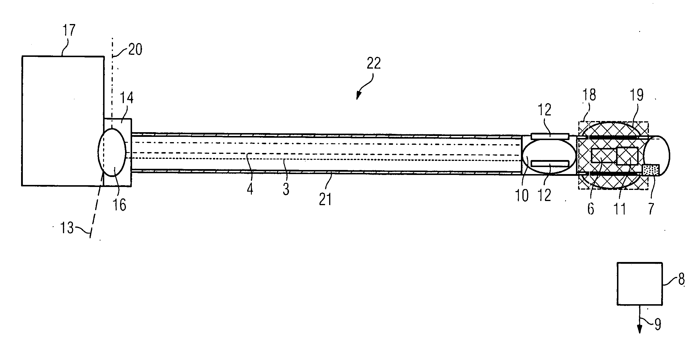
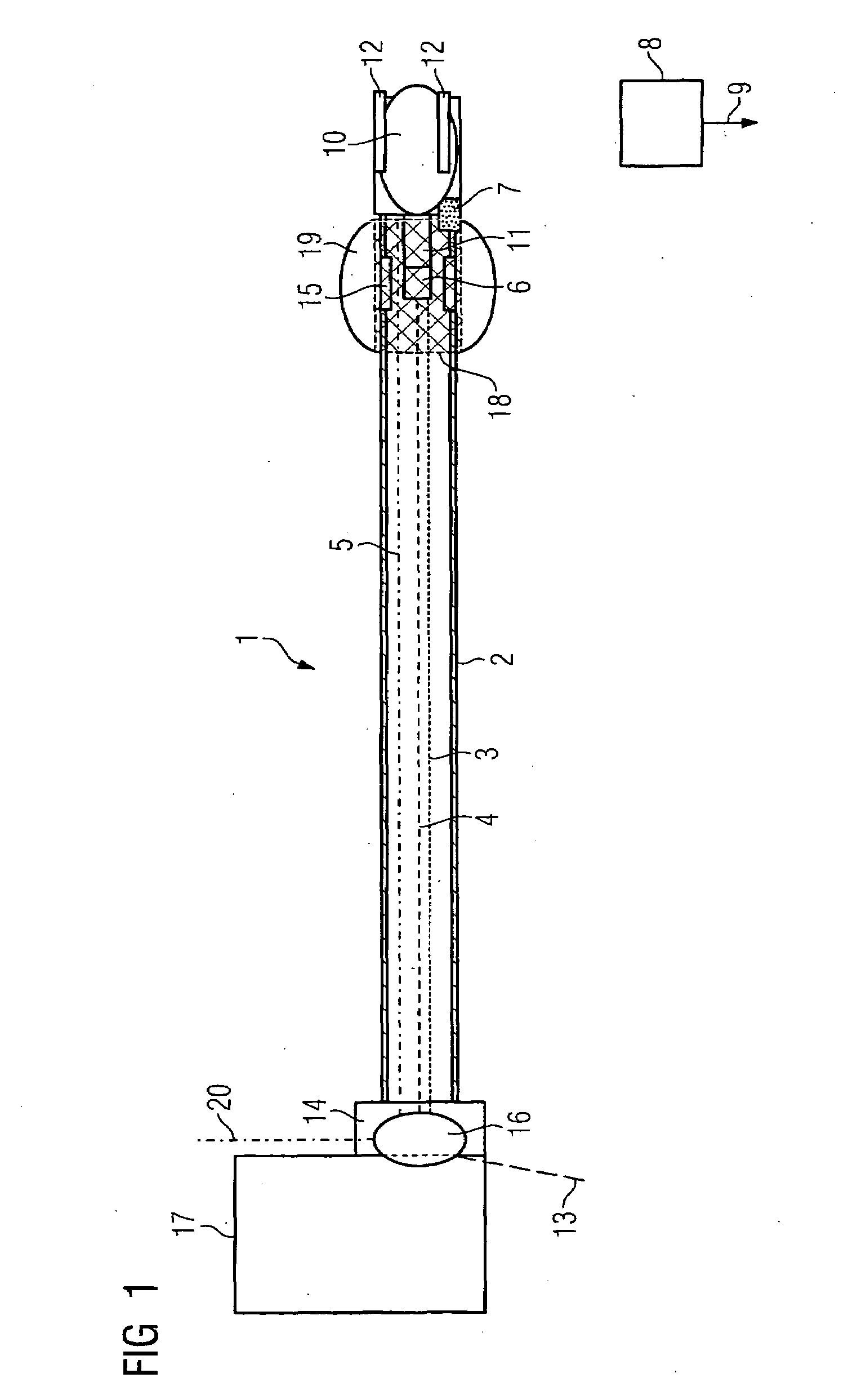
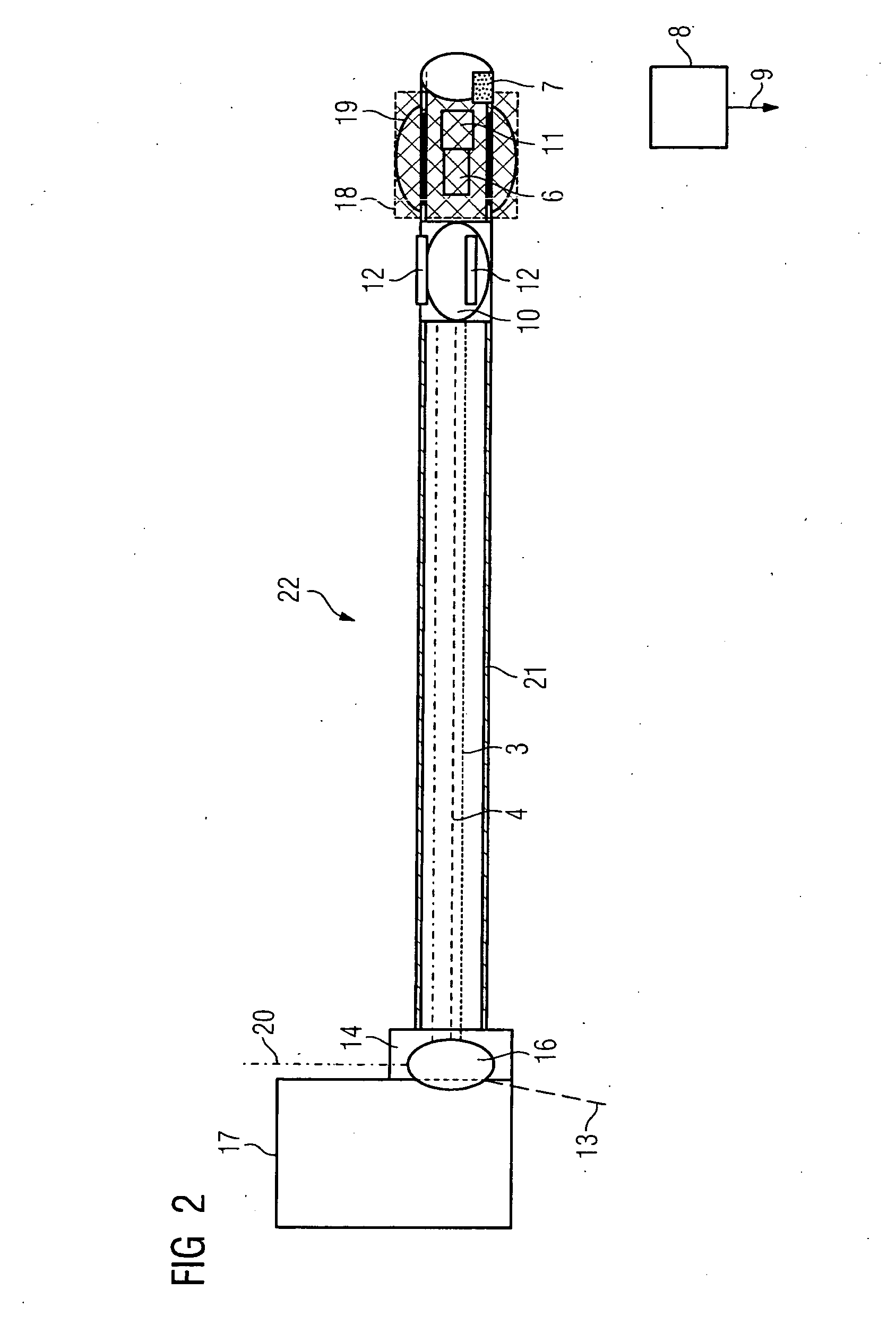
[0058]FIG. 1 shows an inventive device 1 with a cutting-balloon catheter. The inventive device 1 has a hollow flexible drive shaft 2 in which are integrated an OCT signal lead 3 and an IVUS signal lead 4. The OCT signal lead 3 is therein embodied as a glass-fiber lead. Further located in the flexible drive shaft 2 is a signal lead 5 of the position-sensor system embodied as an electromagnetic sensor system. Thus what results through the surrounding drive shaft 2 is an integrated unit that replaces the separate catheter used hitherto in favor of better image monitoring and treating of vascular occlusions.

[0059]What is to be preferred is an embodiment, not shown here, in which it is not the drive shaft 2 that rotates but only the IVUS and OCT sensor in order thereby, where applicable, to avoid friction between the catheter device and the vessel's interior wall and simultaneously cause the OCT sensor to turn.

[0060]The signal lead 5 of the electromagnetic position-sensor system leads to...


PUM


Abstract

The invention relates to a device for performing a cutting-balloon intervention that includes a cutting-balloon catheter with an expandable balloon having axially arranged knives, with the cutting-balloon catheter having a pre-mounted stent.

Description

CROSS REFERENCE TO RELATED APPLICATIONS[0001]This application claims priority of German application No. 10 2006 002 898.8 filed Jan. 20, 2006, which is incorporated by reference herein in its entirety.FIELD OF THE INVENTION[0002]The invention relates to a device for performing a cutting-balloon intervention that includes a cutting-balloon catheter with an expandable balloon having axially arranged knives. The invention relates further to an associated x-ray apparatus.BACKGROUND OF THE INVENTION[0003]Vascular diseases are among the commonest disorders having a fatal outcome. Warranting particular mention is myocardial infarction due to diseased coronary vessels. Arteriosclerotic plaque results in more or less severe blocking of the coronary vessels.[0004]Various methods have been developed in recent years for treating such cases of narrowing of, for example, coronary vessels or other parts of the vascular system. Such treatment attempts to clear the plaque away or, as the case may be...

Claims


Application Information

Patent Timeline
Patent Type & Authority Applications(United States)
IPC IPC(8): A61F2/06A61F2/958
CPCA61B5/0066A61B6/5247A61B5/0402A61B5/08A61B5/411A61B5/7207A61B6/03A61B8/12A61B8/42A61B17/320725A61B19/2203A61B19/5244A61B2017/00004A61B2017/00057A61B2017/00106A61B2017/00778A61B2017/00893A61B2017/22001A61B2017/22002A61B2017/22061A61B2019/2211A61B2019/5238A61B2019/5251A61B2019/5278A61F2/958A61M25/10A61M25/104A61M2025/1086A61M2025/109A61B6/4417A61B5/02007A61B2090/3782A61B34/20A61B2034/301A61B2090/376A61B34/30A61B2034/2051A61B5/318
Inventor MASCHKE, MICHAEL
Owner SIEMENS HEALTHCARE GMBH
Why Eureka
Try Eureka