Model-based inlet air dynamics state characterization

Active Publication Date: 2007-08-02
GM GLOBAL TECH OPERATIONS LLC
View PDF11 Cites 4 Cited by
  • Summary
  • Abstract
  • Description
  • Claims
  • Application Information

AI Technical Summary

Benefits of technology

[0005] Accordingly, the present invention provides an engine control system that includes an exhaust gas recirculation (EGR) valve. The engine control system further includes a first module that determines an EGR erro

Problems solved by technology

During transient maneuvers, the required amount of EGR and the actually achieved EGR may differ as a result of delays in the engine system.
In some cas

Method used


Image

  • Model-based inlet air dynamics state characterization
  • Model-based inlet air dynamics state characterization
  • Model-based inlet air dynamics state characterization

Examples


Example

[0014] The following description of the preferred embodiment is merely exemplary in nature and is in no way intended to limit the invention, its application, or uses. For purposes of clarity, the same reference numbers will be used in the drawings to identify similar elements. As used herein, the term module refers to an application specific integrated circuit (ASIC), an electronic circuit, a processor (shared, dedicated, or group) and memory that execute one or more software or firmware programs, a combinational logic circuit, and / or other suitable components that provide the described functionality.

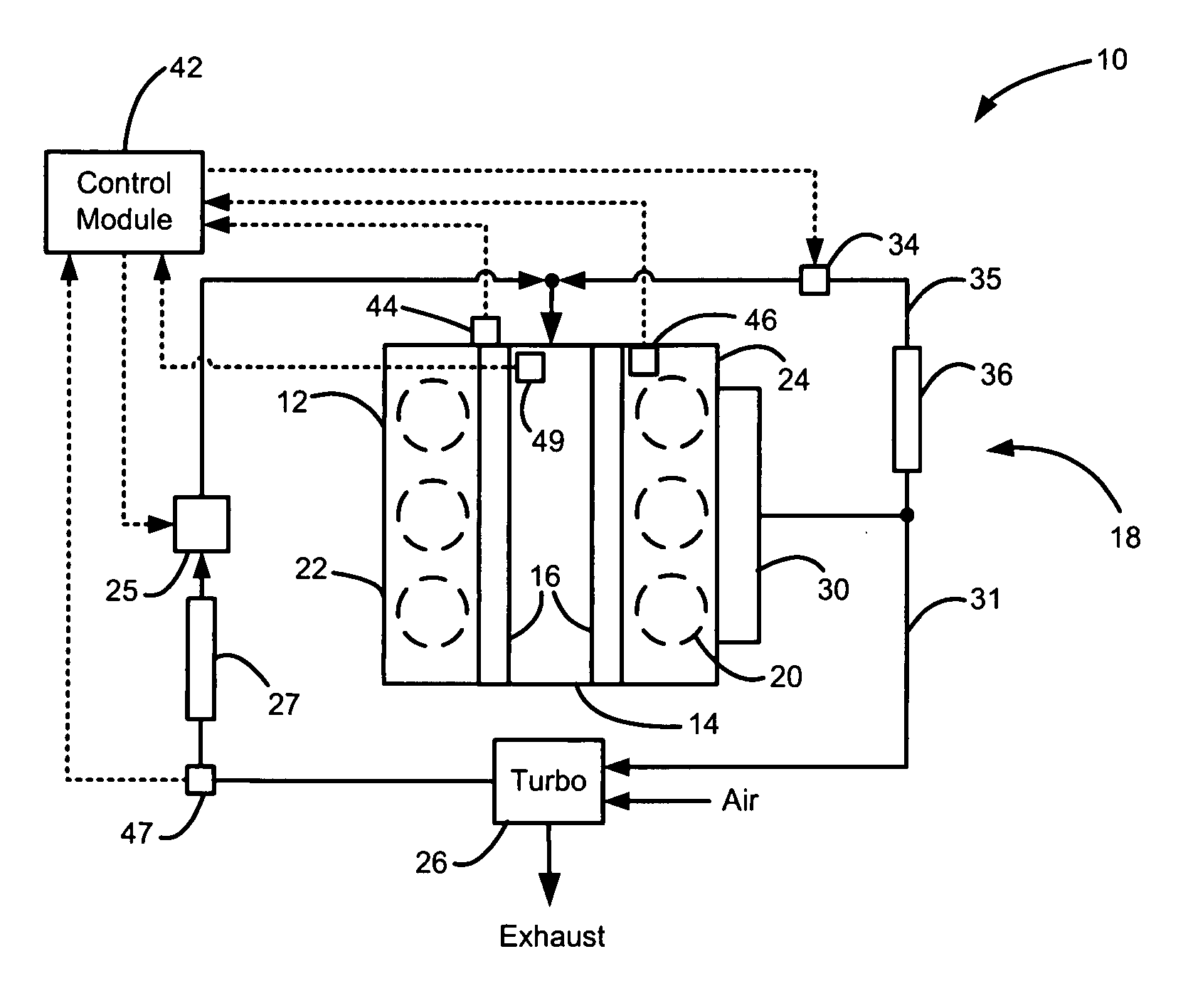
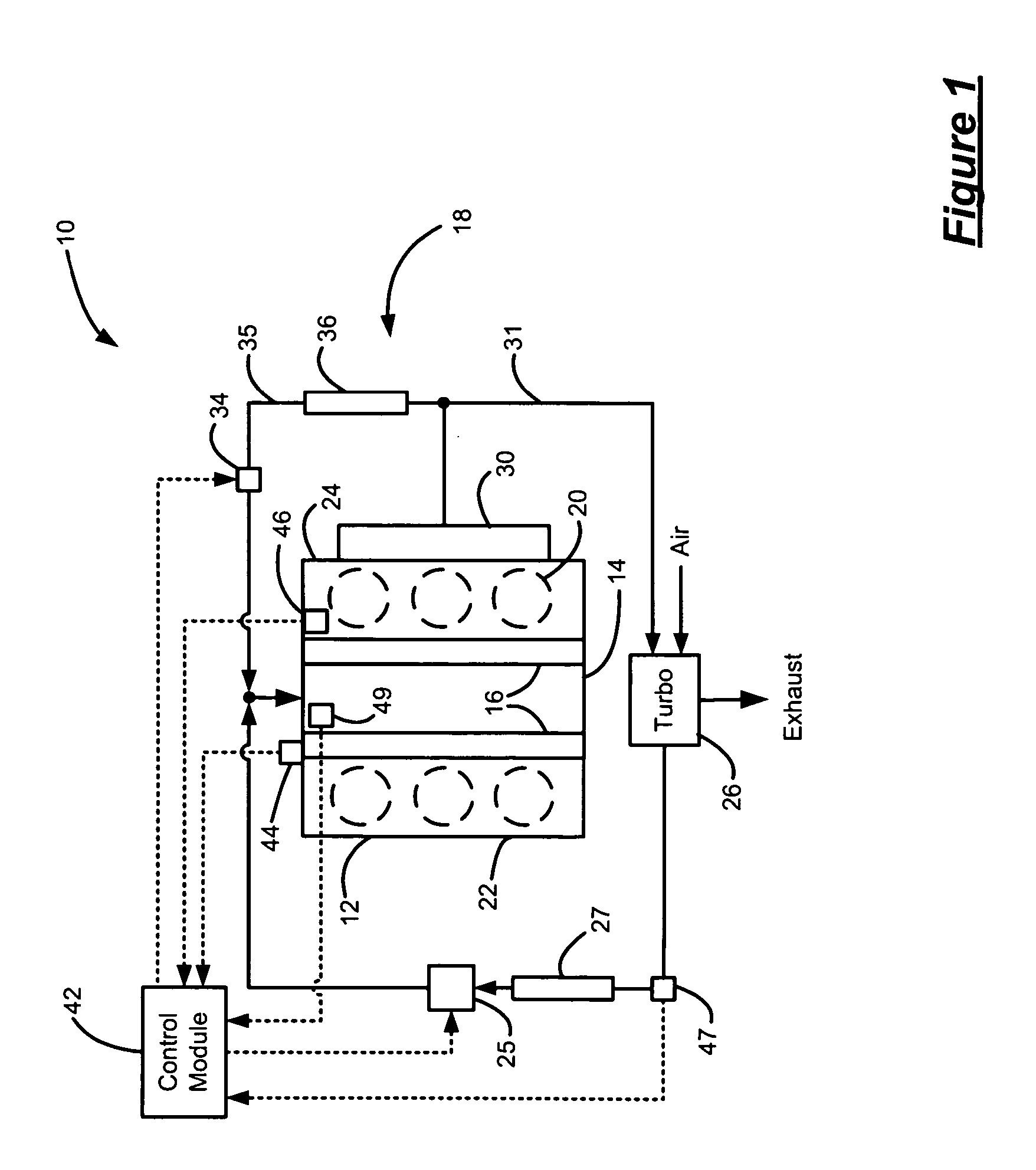
[0015] Referring now to FIG. 1, an exemplary engine system 10 is schematically illustrated in accordance with the present invention. The engine system 10 includes an engine 12, an intake manifold 14, a fuel injection system 16 and an exhaust system 18. The exemplary engine 12 includes six cylinders 20 configured in adjacent cylinder banks 22, 24 in V-type layout. Although FIG. 1 depict...


PUM


Abstract

An engine control system that having an exhaust gas recirculation (EGR) valve includes a first module that determines an EGR error and a second module that calculates a fuel injection timing based on the EGR error. Operation of an engine is regulated based on the fuel injection timing to reduce emissions during transient operation of the engine.

Description

FIELD OF THE INVENTION [0001] The present invention relates to internal combustion engines, and more particularly to a combustion control for reducing engine emissions. BACKGROUND OF THE INVENTION [0002] Internal combustion engines combust an air and fuel mixture to generate drive torque. More specifically, air is drawn into the engine and is mixed with fuel. The air and fuel mixture is combusted within cylinders to drive a crankshaft, producing drive torque. Mass airflow into the engine and the quantity of fuel injected determine the amount of drive torque generated. [0003] Some engines include exhaust gas recirculation (EGR) systems to improve engine operation and reduce engine emissions. The EGR system includes an EGR valve that regulates an amount of exhaust gas that is circulated back to the intake manifold. The additional exhaust gas affects the amount of engine air intake through the throttle. EGR is the most efficient means to reduce overall emissions. Large amounts of EGR (...

Claims


Application Information

Patent Timeline
IPC IPC(8): F02M51/00F02M25/07G06F17/00F02B47/08
CPCF02B47/08F02D41/0072F02D41/345Y02T10/47F02M25/0727Y02T10/44F02M25/0707F02M26/05F02M26/23Y02T10/40
Inventor YANAKIEV, OGNYAN N.LIN, CHAN-CHIAOEL TAHRY, SHERIF H.
Owner GM GLOBAL TECH OPERATIONS LLC
Why Eureka
Try Eureka