Multi-reflecting Time-of-flight Mass Spectrometer With Orthogonal Acceleration

a mass spectrometer and orthogonal acceleration technology, applied in mass spectrometers, separation processes, dispersed particle separation, etc., can solve the problems of limiting the duty cycle of the trap, introducing additional ion losses, and several percen

Active Publication Date: 2007-08-02
LECO CORPORATION
View PDF26 Cites 124 Cited by
  • Summary
  • Abstract
  • Description
  • Claims
  • Application Information

AI Technical Summary

Benefits of technology

[0021] These and other features, advantages, and objects of the present invention will be further understood and appreciated by those skilled in the art by reference to the following specification, claims, and appended drawings.

Problems solved by technology

.), an ion trap source introduces at least two significant problems: 1) ion scattering on gas; and 2) space charge effects on ion beam parameters.
An automatic adjustment of peak intensity would stabilize mass scale, but will introduce additional ion losses and limit a duty cycle of the trap (efficiency of converting continuous ion beams into ion pulses) to several percent.
The solution still has drawbacks related to ion scattering on gas, slow pulsing and, as a result, a large load on the detector and the data acquisition system, currently known to have a limited dynamic range.
Unfortunately, the conventional orthogonal acceleration scheme is poorly applicable to MR-TOF because of two reasons:
This solution, however, is not suitable for ion injection into an MR-TOF MS because ions of different masses gain different energies during bunching and thus are orthogonally accelerated under essentially different angles with respect to the direction of the continuous ion beam.
However, ion sources of the prior art do not provide a sufficient duty cycle above several percent, or suffer other drawbacks.

Method used


Image

  • Multi-reflecting Time-of-flight Mass Spectrometer With Orthogonal Acceleration
  • Multi-reflecting Time-of-flight Mass Spectrometer With Orthogonal Acceleration
  • Multi-reflecting Time-of-flight Mass Spectrometer With Orthogonal Acceleration

Examples


Embodiment Construction

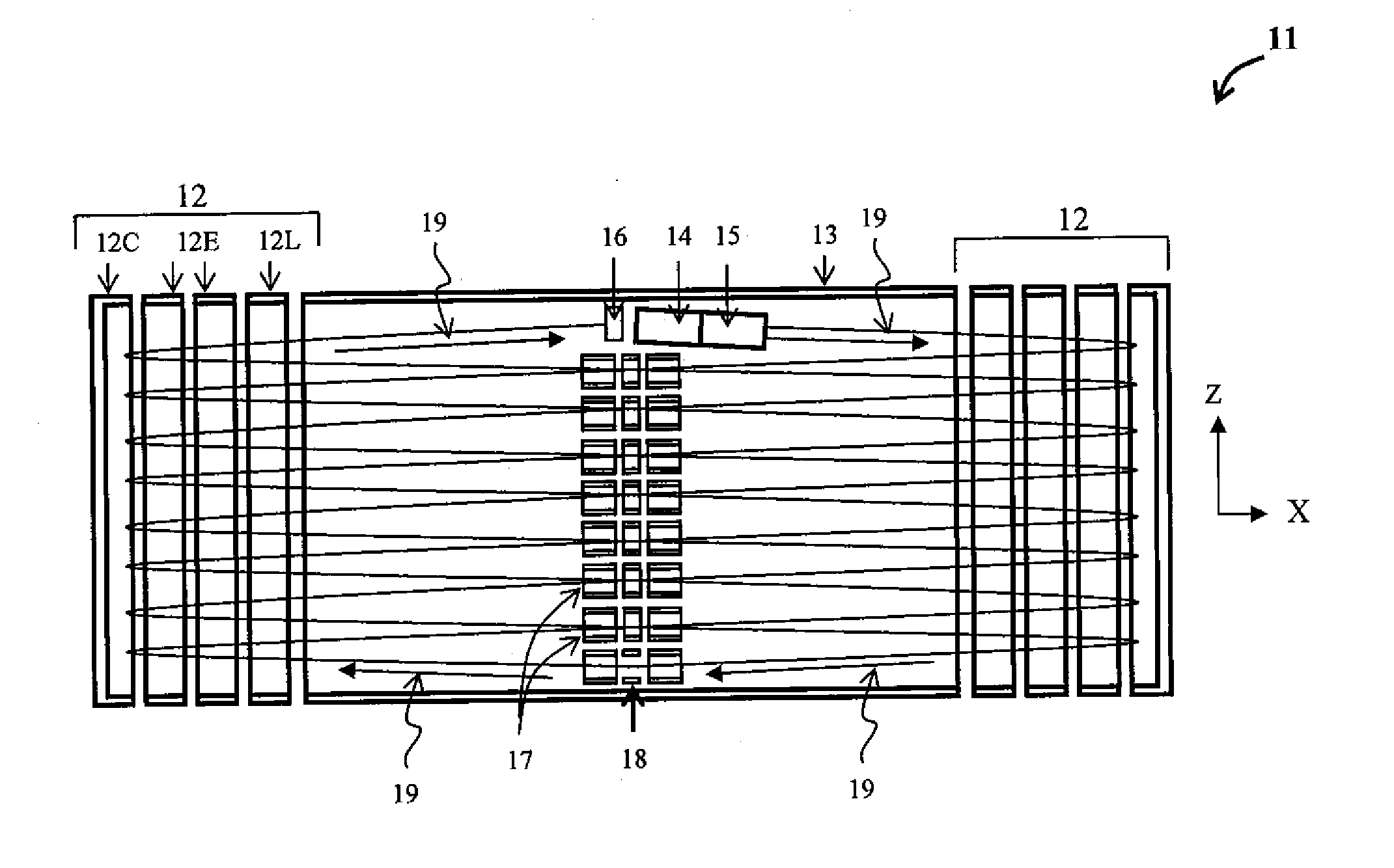
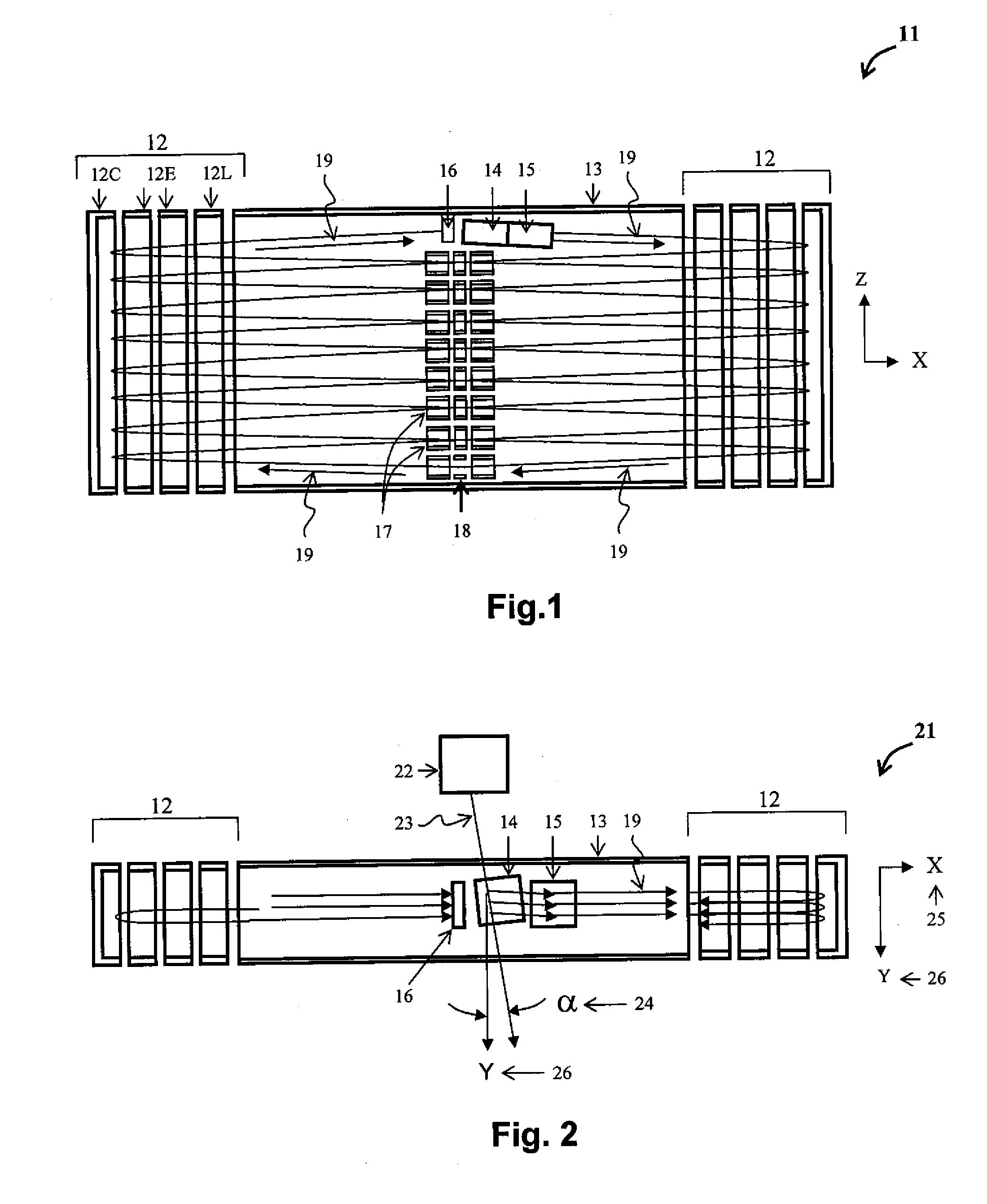
[0032] The inventors have found multiple related ways of improving the duty cycle of orthogonal injection into the MR-TOF MS. For one, the continuous ion beam may be oriented substantially across the plane of the jig-saw folded ion path, which will allow extending the length of ion packets in the orthogonal accelerator. The ion beam is slightly tilted to normal axis, and ion packets are steered back into the symmetry plane of the folded ion path, thus mutually compensating time distortions of the tilt and the steering (FIGS. 1 and 2).

[0033] According to the first aspect of present invention, a multi-reflecting time-of-flight mass spectrometer (MR-TOF MS) comprises: an ion source for generating an ion beam; a subsequent orthogonal accelerator (OA) to convert said ion beam into ion packets; a pair of parallel electrostatic mirrors (orthogonal to axis X); and substantially extended in one direction (Z) to provide a non-overlapping jig-saw path, wherein said ion beam and said accelerat...


PUM


Abstract

The disclosed apparatus includes a multi-reflecting time-of-flight mass spectrometer (MR-TOF MS) and an orthogonal accelerator. To improve the duty cycle of the ion injection at a low repetition rate dictated by a long flight in the MR-TOF MS, multiple measures may be taken. The incoming ion beam and the accelerator may be oriented substantially transverse to the ion path in the MR-TOF, while the initial velocity of the ion beam is compensated by tilting the accelerator and steering the beam for the same angle. To further improve the duty cycle of any multi-reflecting or multi-turn mass spectrometer, the beam may be time-compressed by modulating the axial ion velocity with an ion guide. The residence time of the ions in the accelerator may be improved by trapping the beam within an electrostatic trap. Apparatuses with a prolonged residence time in the accelerator provide improvements in both sensitivity and resolution.

Description

CROSS-REFERENCE TO RELATED APPLICATION [0001] This application claims the benefit of U.S. Provisional Application No. 60 / 725,560, filed on Oct. 11, 2005, the entire disclosure of which is incorporated herein by reference.BACKGROUND OF THE INVENTION [0002] The invention generally relates to the area of mass spectroscopic analysis, and more particularly is concerned with method and apparatus, including multi-reflecting time-of-flight mass spectrometer (MR-TOF MS) and with the apparatus and method of improving the duty cycle of the orthogonal injection at a low repetition rate. [0003] Time-of-flight mass spectrometers (TOF MS) are increasingly popular, both as stand-alone instruments and as a part of mass spectrometry tandems like a Q-TOF or a TOF-TOF. They provide a unique combination of high speed, sensitivity, resolving power (resolution) and mass accuracy. Recently introduced multi-reflecting time-of-flight (MR-TOF) mass spectrometers demonstrated a substantial raise of resolution ...

Claims


Application Information

Patent Timeline
Patent Type & Authority Applications(United States)
IPC IPC(8): H01J49/00
CPCH01J49/406H01J49/401
Inventor VERENTCHIKOV, ANATOLI N.
Owner LECO CORPORATION
Why Eureka
Try Eureka