MIMO antenna configuration

a technology of mimo and antenna, applied in the direction of resonant antennas, independent non-interacting antenna combinations, basic electric elements, etc., can solve the problems of poor system efficiency, higher cost, and more complex system mechanics, and achieve good mimo performance, high hemispherical coverage, and equal and sufficient far spacing

Inactive Publication Date: 2007-08-02
ACCTON TECHNOLOGY CORPORATION
View PDF3 Cites 28 Cited by
  • Summary
  • Abstract
  • Description
  • Claims
  • Application Information

AI Technical Summary

Benefits of technology

[0020] Another advantage of the present invention is equal and sufficient far spacing between any pairs of cubical 4×4 MIMO multiple Antennas provides equal and best non-correlation and orthogonality between them. Because, the structure of the present invention gives isotropic (or equal spread in solid angle) distribution of incoming multipath waves, and also gives evenly-dispersive (or equal spread in time delay) distribution of incoming multipath waves.
[0021] Besides, the structure of the present invention provides high hemispherical coverage; Good MIMO performance in ceiling or desktop mounts, which give AP equal spatial-multiplexing and antenna-diversity in elevation in addition to azimuth.
[0022] And the present invention also provides symmetrically in three 120° sectors; deployment fitted in cellular form which is effective to AP frequency reuse.
[0023] The main purpose of the present invention is to provide A structure for MIMO multiple antennas system, comprises: a housing for containing electronics communication modules; a dipole antenna connected to the housing and stands vertically; and three PIFAs connected to a PCB of the electronics communication modules within the housing, wherein the distances between the dipole antenna and each one of three PIFAs are equal.
[0024] The housing is a box shaped with a rectangular cross section. The dipole antenna stands outside of said housing. The shape of said housing includes a tetrahedron, a dome, a pyramid or a cube. The dipole antenna stands inside of said housing. The three PIFAs are located on a loop that approximately forms a triangle. The triangle is regular triangle. The distances between said dipole antenna and each one of said PIFAs are greater than 1 λ and less than 10 λ in typical indoor MIMO area for AP. The distances between said dipole antenna and each one of said PIFAs are greater than 100 λ in typical outdoor MIMO area for AP. The three PIFAs are attached on a co-planar surface within said housing.

Problems solved by technology

The disadvantage of the antenna structures of the 4×4 MIMO system shown from FIG. 1 to FIG. 11 is that the efficiency of the system is poor.
Furthermore, the system is more complex in mechanics and the cost is higher.

Method used


Image

  • MIMO antenna configuration
  • MIMO antenna configuration
  • MIMO antenna configuration

Examples


Embodiment Construction

[0040] Method and structure for manufacturing a MIMO antenna is described below. In the following description, numerous specific details are set forth in order to provide a thorough understanding of the present invention, and the scope of the present invention is expressly not limited expect as specified in the accompanying claims.

[0041] According to the design rule for MIMO antenna, the spacing between transmit and receive antenna must be wide enough for enhancing the transmission rate of the MIMO system. Besides, the system must satisfied orthogonality condition of MIMO antennas. The transmission antenna spacing St must larger than 100 λ in the outdoor environment. The transmission antenna spacing St must larger than 1 λ, and smaller than 10 λ at indoor environment.

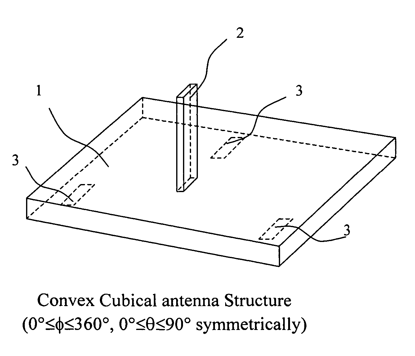
[0042] Referring to FIG. 12, it shows a convex cubical antenna structure for MIMO multiple antennas according to the preferred embodiment of the present invention. A dipole antenna 2 stands vertically on the surface o...


PUM


Abstract

The present invention provides a MIMO antenna structure and design. A single dipole antenna stands at the center of a triangle which is formed by three PIFAs antennas, and the three PIFA antennas has equal squint angle relative to the neighbors, that is there is 120° sector angle between any two PIFA axes of three such that the dipole and the other PIFAs forms a tetrahedron. The MIMO antenna structure of the present invention is simpler in mechanics but high efficiency in performance.

Description

BACKGROUND OF THE INVENTION [0001] 1. Field of the Invention [0002] This invention relates to a structure for antenna, and more especially, to the antenna configuration for the access point (AP) adapted to the wireless local-area network (WLAN) or wireless metropolitan area network (WMAN). [0003] 2. Description of the Prior Art [0004] Wireless communication systems have been developed rapidly. No matter in the business or in the family, the wireless communication systems are everywhere in people's life and are widely employed to provide various types of communication such as voice, data, and so on. [0005] A multiple-input multiple-output (MIMO) communication system employs multiple transmit antennas and multiple receive antennas for transmission and reception of spatial-multiplexing data streams. In a point-to-point system, the data streams are transmitted to or received from a single terminal. However, a multiple access communication system having a base station may also concurrent...

Claims


Application Information

Patent Timeline
Patent Type & Authority Applications(United States)
IPC IPC(8): H01Q1/24
CPCH01Q9/0421H01Q21/28H01Q9/16
Inventor LIU, I-RU
Owner ACCTON TECHNOLOGY CORPORATION
Why Eureka
Try Eureka