
Image Processing method and image processor

a processing method and image technology, applied in the field of image processing, can solve the problems of requiring enormous efforts, difficult for a first-timer to set the illumination condition, and the algorithm becomes complicated, so as to reduce the cost of manufacturing the processor, suppress the capacity of data to be processed, and accurately extract an area

Inactive Publication Date: 2007-08-02
ORMON CORP
View PDF1 Cites 39 Cited by
  • Summary
  • Abstract
  • Description
  • Claims
  • Application Information

AI Technical Summary

Benefits of technology

[0017] Further, an object of the present invention is to make an algorithm in the conventional two-dimensional image processing applicable as it is, to eliminate the need for development of new software as well as the need for improvement in performance of hardware, so as to suppress cost.
[0032] In another mode of the first image processing method, a step of displaying an image on the basis of the image data generated in the second step is executed. Thereby, it is possible to visually realize the surface state of the object represented by the normal vector.
[0039] According to the second image processing method, it is possible to generate image data reflecting the reflectivity of the object surface can be generated without detailed adjustment of the illumination. Hence, for example in the case of detecting a region having a different reflectivity from, while having the same color as, surroundings of that region, it is possible to accurately detect a region to be detected without the need for detailed adjustment of the illumination.
[0042] According to this mode, in the case of testing a prescribed area on the object surface, a measurement process and a determination process are executed after extraction of a characteristic showing an area to be tested from the one-dimensional information reflecting the normal vector or the reflectivity, whereby it is possible to execute accurate testing.
[0046] According to the above mode, any one pickup element is driven to execute the image pickup process every time the illuminating means is lighted, and outputting an image signal is held until completion of image pickup in the final pickup element. Therefore, even when a moving body is an object to be measured, the object to be measured is made to stand still for a given short time to generate an image necessary for measurement. Further, when positional displacement at every image pickup timing falls within a range of the resolution of the image pickup element, it is possible to perform image pickup while moving the object to be measured.
[0048] According to the present invention, after a normal vector or a reflectivity of the surface of an object is obtained, one-dimensional information reflecting the measurement result is obtained, and image data is generated according to this one-dimensional information to extract a characteristic by means of two-dimensional image processing, whereby it is possible to accurately extract an area to be detected without detailed adjustment of an illumination condition. Further, the same algorithm as in the conventional two-dimensional image processing can be applied, whereby it is possible to suppress a capacity of data to be processed and further to utilize a software resource used in the two-dimensional image processing, so as to substantially reduce cost in manufacturing of the processor.

Problems solved by technology

However, since such setting requires wide knowledge as well as experience, it is difficult for a first-timer to set the illumination condition.
There further is a problem in that even those experienced with wide knowledge are required to perform operations by trial and error for appropriately setting the illumination condition, thereby requiring enormous efforts.
On the other hand, according to the photometric stereo method, although it is possible to obtain three-dimensional data representing the surface shape of the object without precise adjustment of the illumination condition, an algorithm becomes complicated since performing a three-dimensional measurement process is necessary.
This raises the possibility of a delay in the process, and prevention of such a delay requires improvement in performance of hardware.
Moreover, since an algorithm developed for the conventional two-dimensional image processing cannot be applied, it is necessary to develop new software, which might also cause a steep increase in cost.

Method used


Image

  • Image Processing method and image processor
  • Image Processing method and image processor
  • Image Processing method and image processor

Examples


first embodiment

(i) First Embodiment

[0087] In the present embodiment, as shown in FIG. 4, one out of the three components nX, nY, nZ of the normal vector n* is used as the one-dimensional information.

[0088] This one-dimensional information is useful in extracting inclination of the surface work along any of the axes X, Y, Z.

[0089] For example, as shown in FIG. 5, when the X-axis is set in a direction along a width direction of a cylindrical work W1, the Y-axis is set in a direction along a length direction of the work W1, and the Z-axis is set in a direction along a height direction of the work W1 with respect to the work W1, it is possible to obtain an image reflecting a change in inclination angle of the surface of the work W1 by setting the component nX of the X-axis of the normal vector n* as the one-dimensional information.

[0090]FIG. 6 shows an image generated by the component nX in the X-axis direction in the setting example of FIG. 5. It is to be noted that also in the present embodiment,...

second embodiment

(ii) Second Embodiment

[0094] In the present embodiment, as shown in FIG. 7, a direction shown by an arbitrary vector A* of the space coordinate system is considered as a reference direction, and the length U of a projection pattern obtained when a normal vector n* is projected in the reference direction is used as the one-dimensional information.

[0095] The one-dimensional information U can be used for example for a process of detecting a region the inclination of which against the X-Y plane is in a prescribed angle range out of regions on the surface of the work W. For example, the one-dimensional information U of each pixel is obtained with the normal line direction of the level plane having a reference inclination taken as the vector A*, and an assembly of pixels with the U values exceeding a prescribed threshold can be detected as a target region.

[0096] It is to be noted that the one-dimensional information U can be obtained such that the vector A* is taken as a unit vector and...

third embodiment

(iii) Third Embodiment

[0097]FIG. 8 shows an example of obtaining angle information on the normal vector n* as one-dimensional information. In the present embodiment, an angle θ of the normal vector n* against the X-Y plane and an angle φ of the normal vector n* against the Y-Z plane are obtained. It should be noted that the angle θ is obtained as an angle of a projection pattern against the X-axis when the normal vector n* is projected onto the X-Y plane, and the angle φ is obtained as an angle of a projection pattern against the Y-axis when the normal vector n* is projected onto the Y-Z plane.

[0098] The angle θ is considered to represent the direction of the normal vector n* when the vector is seen from the top, i.e., the direction of the normal vector n* having been projected onto the X-Y plane. The other angle φ is considered to represent the openness degree of the normal vector n* against the level plane (X-Y plane).

[0099] Also in the case of using the above angle information ...


PUM


Abstract

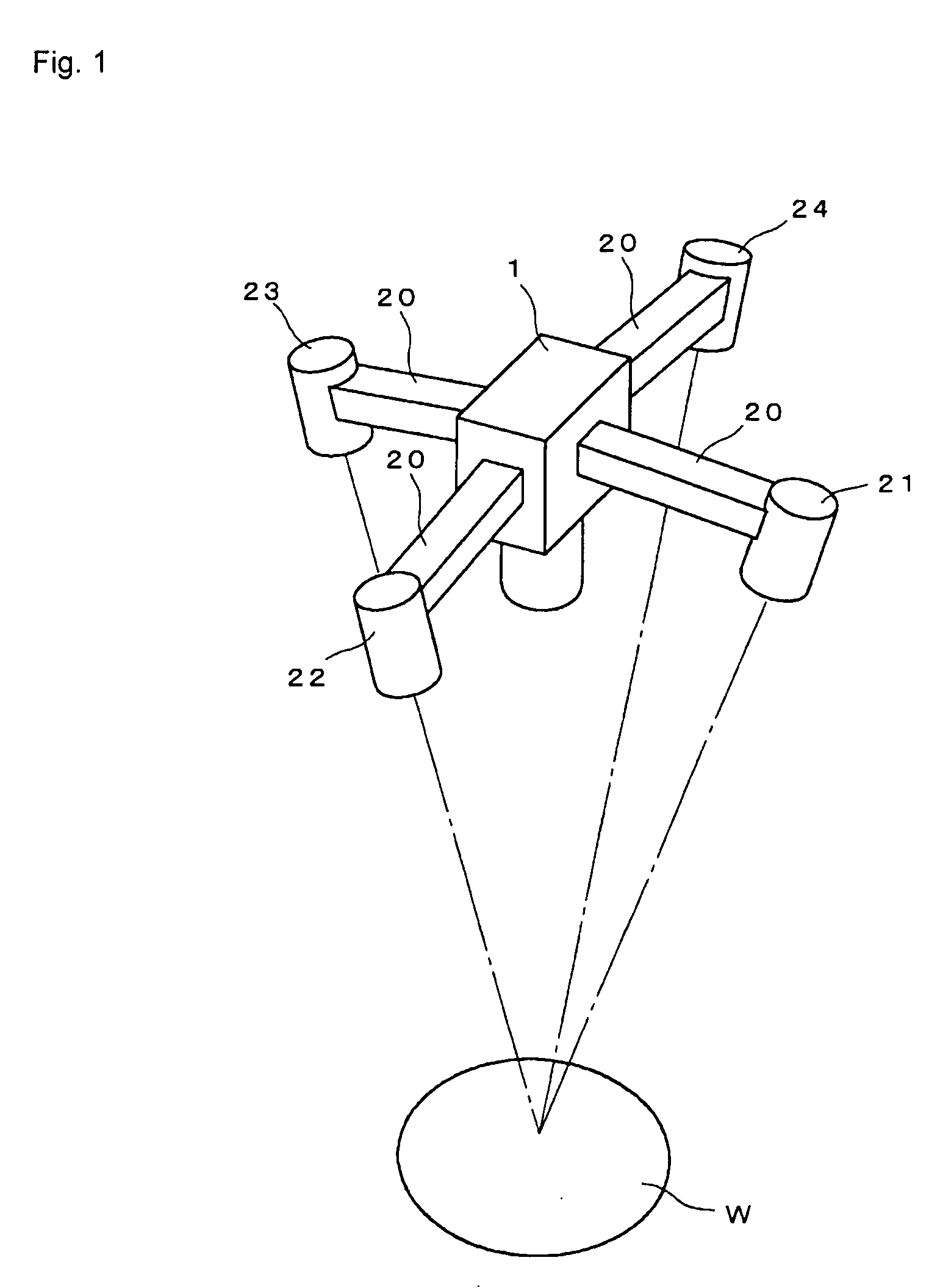
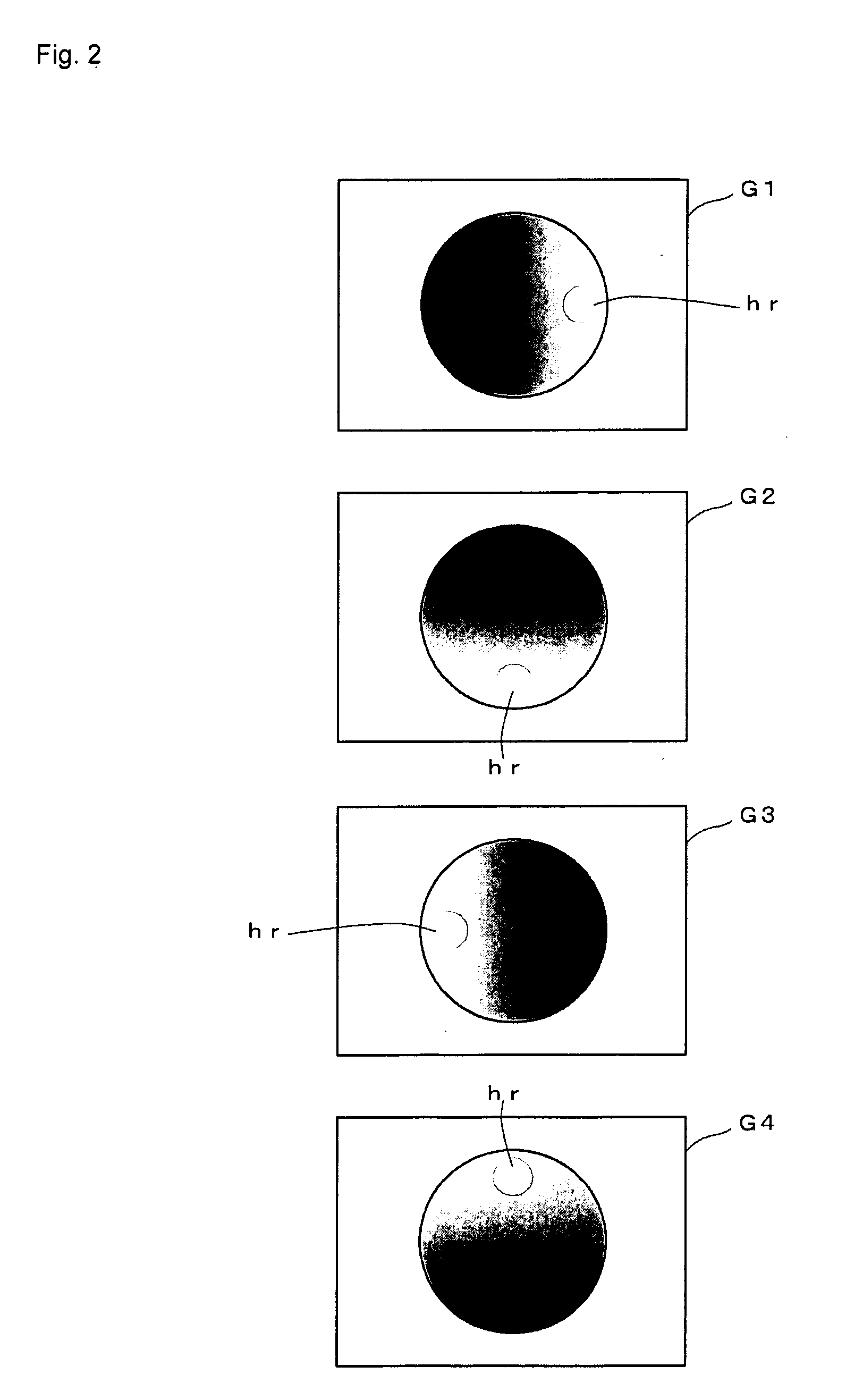
There are provided an image processing method and an image processor for detecting an object to be detected in a simple and accurate manner without detailed adjustment of illumination. Light sources provided in four directions around a camera are sequentially lighted, and a camera is driven every time the one of the light sources is lighted to generate four images of a work. Further, a normal vector of a group of pixels having the same coordinate among the generated images is calculated by use of brightness of each pixel that belongs to the group and a previously obtained illumination direction vector corresponding to each of the light sources. Moreover, the normal vector of each pixel is converted into one-dimensional information showing a relation of the vector with respect to a space coordinate system, and after generation of an image representing the calculation result, a prescribed characteristic extracting process is executed.

Description

[0001] This application claims priority from Japanese patent application JP2006-022295 filed Jan. 31, 2006. The entire content of the aforementioned application is incorporated herein by reference. BACKGROUND OF THE INVENTION [0002] 1. Field of the Invention [0003] The present invention relates to image processing which is executed, in the case of executing processes such as measurement and testing on a prescribed object, as a process prior to those processes. [0004] 2. Description of Related Art [0005] There are many cases where adjustment of illumination is necessary when a surface state of an object is recognized by two-dimensional image processing. For example, in the case of detecting a depression on the surface of an object, it is necessary to provide such illumination as to make the depression darker than other portions. Further, in the case of detecting a letter, a figure or the like, printed on the surface of an object with an uneven surface, it is necessary to select a dir...

Claims


Application Information

Patent Timeline
IPC IPC(8): G06T15/50G01B11/26G01N21/88G06K9/20G06T1/00G06T7/60
CPCG06T7/0073G06T7/586
Inventor KATO, YUTAKAIKEDA, YASUYUKI
Owner ORMON CORP
Learn More