Dynamic fluid control system for immersion lithography

a fluid control system and fluid control technology, applied in the field of immersion lithography, can solve the problems of increasing the depth of focus, difficult to achieve desired results, and difficult to achieve precise equilibrium in practice, and achieve the effect of reducing dynamic forces

Inactive Publication Date: 2007-08-02
NIKON CORP
View PDF17 Cites 18 Cited by
  • Summary
  • Abstract
  • Description
  • Claims
  • Application Information

AI Technical Summary

Benefits of technology

[0017] A dynamic fluid control system and method capable of reducing dynamic forces from the fluid on the last optical element and substrate stage, caused by the motion of the immersion fluid, is disclosed. The system includes an imaging element that defines an image and a stage configured to support a substrate. An optical system is provided to project the image defined by the imaging element onto the substrate. The optical system includes a last optical element. A gap filled with immersion fluid is provided is between the substrate and the last optical element. A dynamic force control system is provided to maintain a substantially constant force on the last optical element and stage by compensating for dynamic changes of the immersion fluid caused by the motion of the immersion fluid through the gap and / or movement of the stage.

Problems solved by technology

Immersion also increases the depth of focus for a given NA, which is the tolerable error in the vertical position of the wafer, compared to a conventional lithography system.
This desired result, however, is very difficult to achieve for a number of reasons.
A precise equilibrium, however, is difficult to achieve in practice.
These waves may cause the last optical element to oscillate up and down as well as perturb the wafer stage.
If the oscillations are still occurring during an exposure due to the lingering effects of the waves, the accuracy and image quality may be adversely affected.
The dynamic forces and pressures acting on the last optical element caused by the motion of the immersion fluid may cause the last optical element to become distorted and / or moved either up or down from its ideal position.
As a result, the last optical element may be out of focus, resulting in a poor exposure.
Such droplets are undesirable.

Method used


Image

  • Dynamic fluid control system for immersion lithography
  • Dynamic fluid control system for immersion lithography
  • Dynamic fluid control system for immersion lithography

Examples


Embodiment Construction

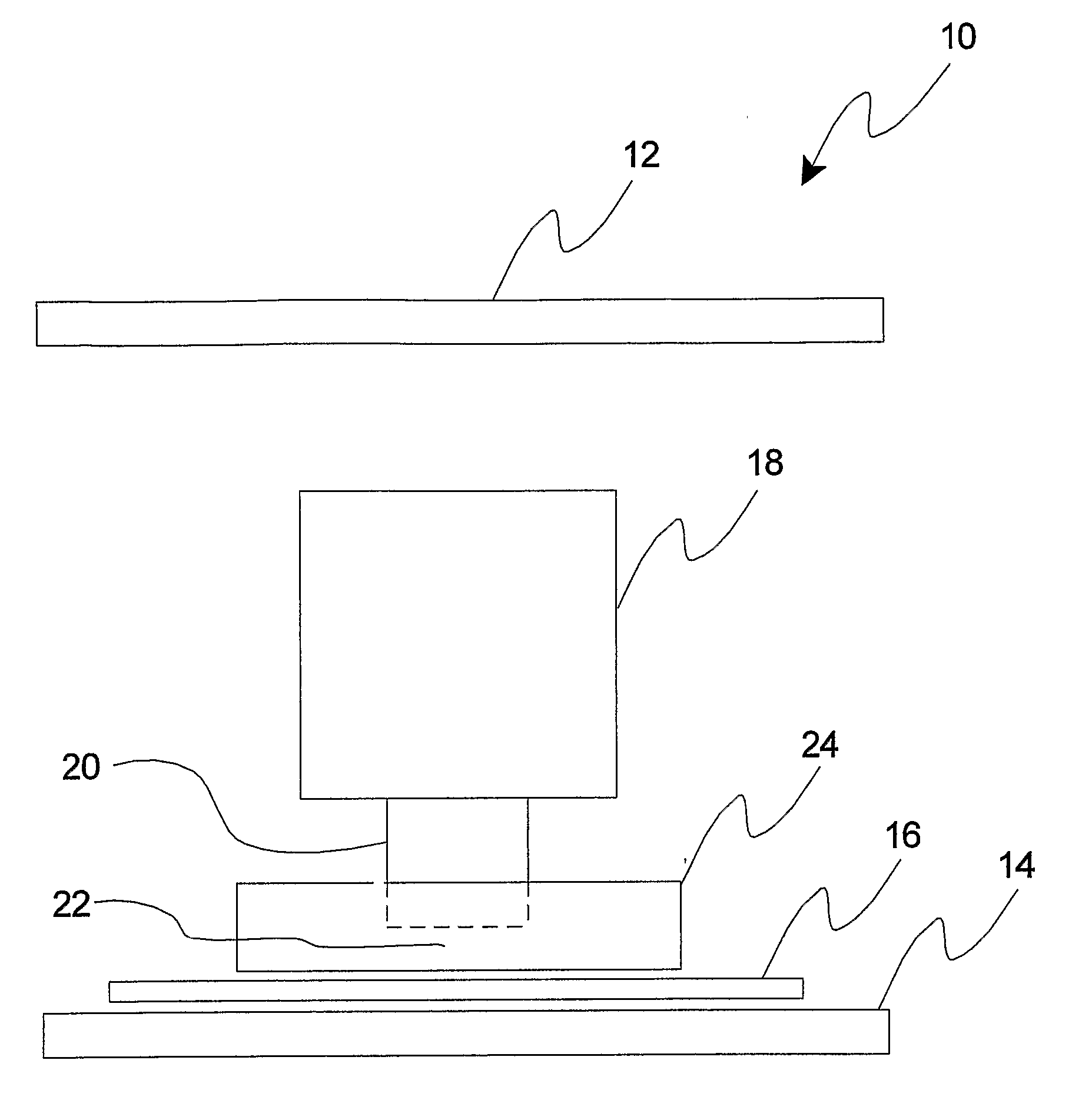
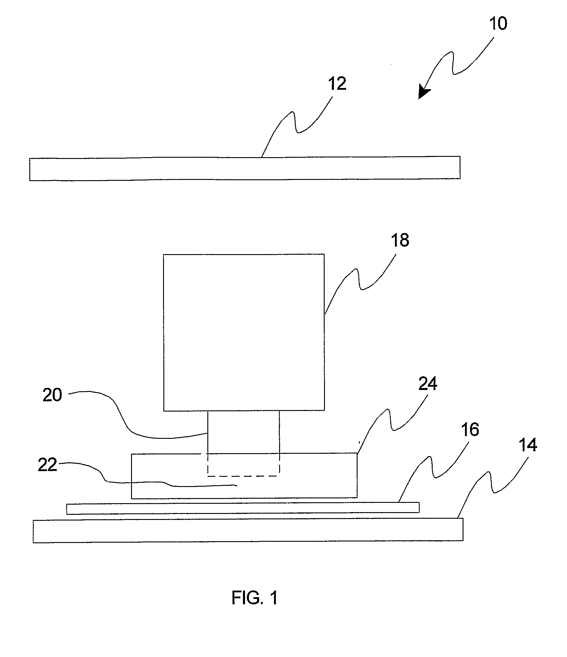
[0029] Referring to FIG. 1, an immersion apparatus is shown. The immersion apparatus 10 includes an imaging element 12 which defines an image, a stage 14 configured to support a substrate 16, and an optical system 18 configured to project the image defined by the imaging element 12 onto the substrate 16. The optical system 18 includes a “last” or “final” optical element 20. A gap 22 is provided between the substrate 16 and the last optical element 20. A fluid injection and removal element 24 provides immersion fluid between the substrate 16 and the last optical element 20.

[0030] In one embodiment, the imaging element 12 is a reticle or mask. In other embodiments, the imaging element is a programmable micro-mirror array capable of generating the image, such as described in U.S. Pat. Nos. 5,296,891, 5,523,193, and PCT applications WO 98 / 38597 and 98 / 330096, all incorporated herein by reference. In one embodiment, the stage 14 is a fine stage that is supported by a coarse stage (not s...


PUM

PropertyMeasurementUnit
Reynolds numberaaaaaaaaaa
forceaaaaaaaaaa
dynamic forceaaaaaaaaaa

Abstract

A dynamic fluid control system and method capable of reducing dynamic forces from the fluid on the last optical element (20) and substrate stage (14) caused by the motion of the immersion fluid. The system includes an imaging element (12) that defines an image and a stage (14) configured to support a substrate (16). An optical system (18) is provided to project the image defined by the imaging element onto the substrate. The optical system (18) includes a last optical element (20). A gap (22) filled with immersion fluid is provided between the substrate (16) and the last optical element (20). A dynamic force control system (34) is provided to maintain a substantially constant force on the last optical element and the stage (14) by compensating for dynamic changes of the immersion fluid caused by the motion of the immersion fluid through the gap and/or movement of the stage.

Description

RELATED APPLICATIONS [0001] This application claims priority on Provisional Application Ser. No. 60 / 584,543 filed on Jul. 1, 2004 and entitled “Fluid Control System for Immersion Lithography Tool”. The contents of Provisional Application Ser. No. 60 / 584,543 are incorporated herein by reference for all purposes.BACKGROUND [0002] 1. Field of the Invention [0003] The present invention relates to immersion lithography, and more particularly, to a dynamic fluid control system and method capable of compensating for dynamic changes in the forces exerted on the last optical element and stage by the immersion fluid caused by the motion of the immersion fluid and movements of the stage. [0004] 2. Related Art [0005] A typical lithography machine includes a radiation source, an imaging element defining an image pattern, an optical system, and a wafer stage to support and move the wafer. A radiation-sensitive material, such as resist, is coated onto the wafer surface prior to placement onto the ...

Claims


Application Information

Patent Timeline
Patent Type & Authority Applications(United States)
IPC IPC(8): G03B27/42C07K16/10G01N33/569
CPCG03D3/02G03F7/70341G03F7/70725G03F7/7085G01N2469/20C07K14/005G01N33/56983C12N2740/15022G01N2333/155G03F7/709G03B27/42
Inventor SOGARD, MICHAEL
Owner NIKON CORP
Why Eureka
Try Eureka