Adjustable pouch forming, filling and sealing apparatus and methods

a pouch and adjustment technology, applied in the field of pouch forming, pouch filling and pouch sealing, can solve the problems of insufficient adjustment provided to provide the extent of pouch width size adjustment now desired in the industry, and the use of the same equipment to form, fill and seal pouches of significantly different widths requires a significant number of major change parts, etc., to achieve the effect of reducing weight and complexity, reducing cost and widening the pitch rang

Active Publication Date: 2007-08-09
R A JONES
View PDF45 Cites 36 Cited by
  • Summary
  • Abstract
  • Description
  • Claims
  • Application Information

AI Technical Summary

Benefits of technology

[0074] In addition, the major knife hub is provided with radially adjustable package guides to handle a range of pouch widths. However, the mechanisms by which the package guides of the major knife hub are radially adjusted is different from that of prior mechanisms. The prior adjustment cones shown in the prior patents are eliminated. Instead, the respective package guides are mounted on threaded, extensible carrier rods having beveled gears on their radially inner ends. Each of these engages a common beveled drive gear which is phase adjustable through the major knife hub structure to change the radial extent and thus the circumferential spacing of the package g

Problems solved by technology

Some prior devices operated on an intermittent basis, which is not generally conducive to efficiency where pouches must be formed, filled and sealed at higher rates than intermittent motion machines can effectively produce.
While such equipment works well for pouches of a given pitch or width, use of the same equipment to form, fill and seal pouches of significantly different widths requires a significant number of major change parts.
In other prior U.S. Pat. Nos. 6,657,165 and 6,917,014, a horizontally oriented sealer wheel is provided with heated sealing lands which have slight radial adjustments to permit some adjustment between the parallel transverse seals, but the adjustment provided is insufficient to provide the extent of pouch width size adjustment now desired in the industry, such as for pouches ranging from about 2.5 inches to about 5.5 inches in major width.
Major change parts are required and the changeover procedures are time consuming, but necessary for a pouch operation with the capacity to handle a wide range of pouch widths.
While prior apparatus has provided some d

Method used


Image

  • Adjustable pouch forming, filling and sealing apparatus and methods
  • Adjustable pouch forming, filling and sealing apparatus and methods
  • Adjustable pouch forming, filling and sealing apparatus and methods

Examples


Embodiment Construction

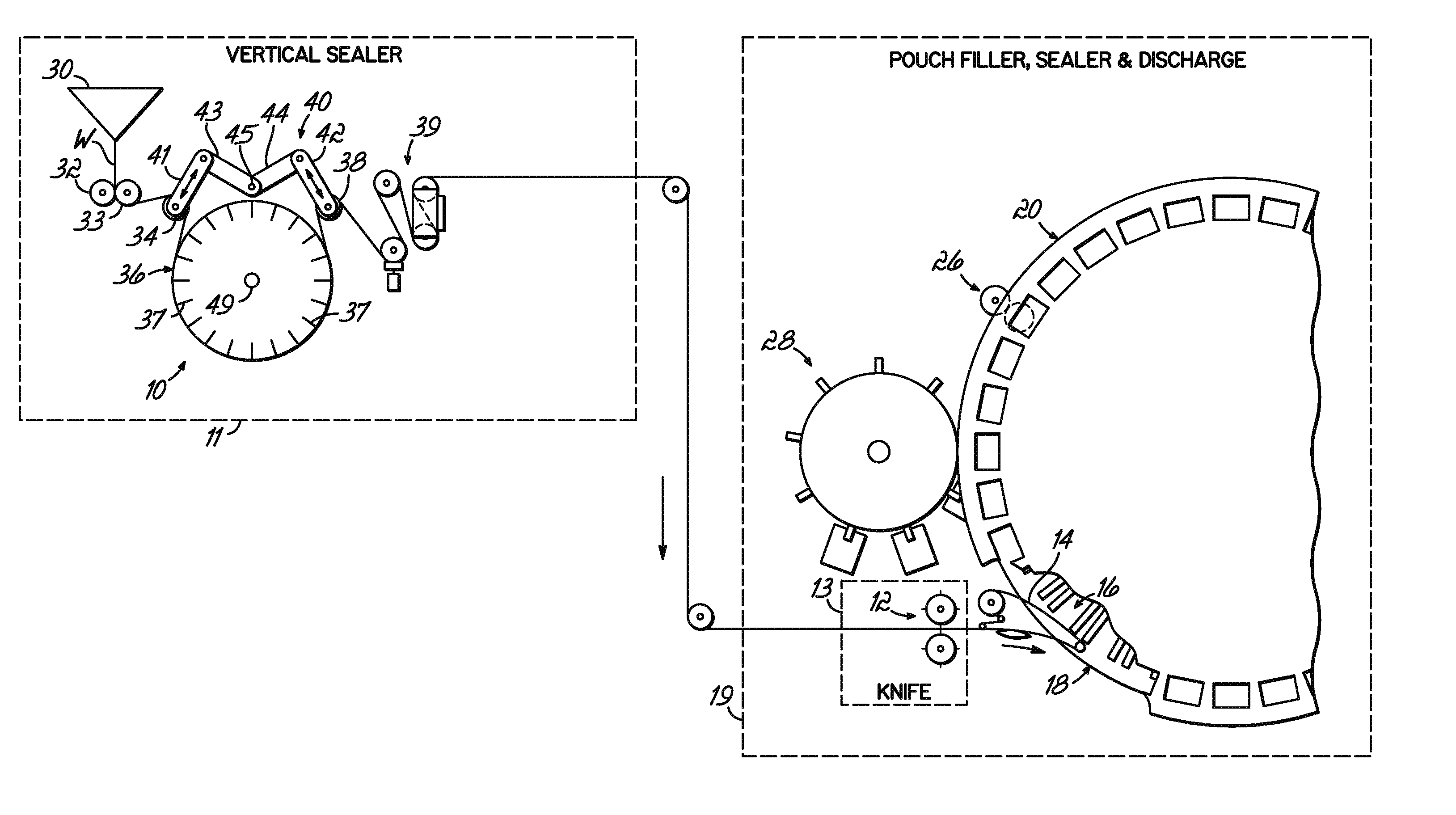
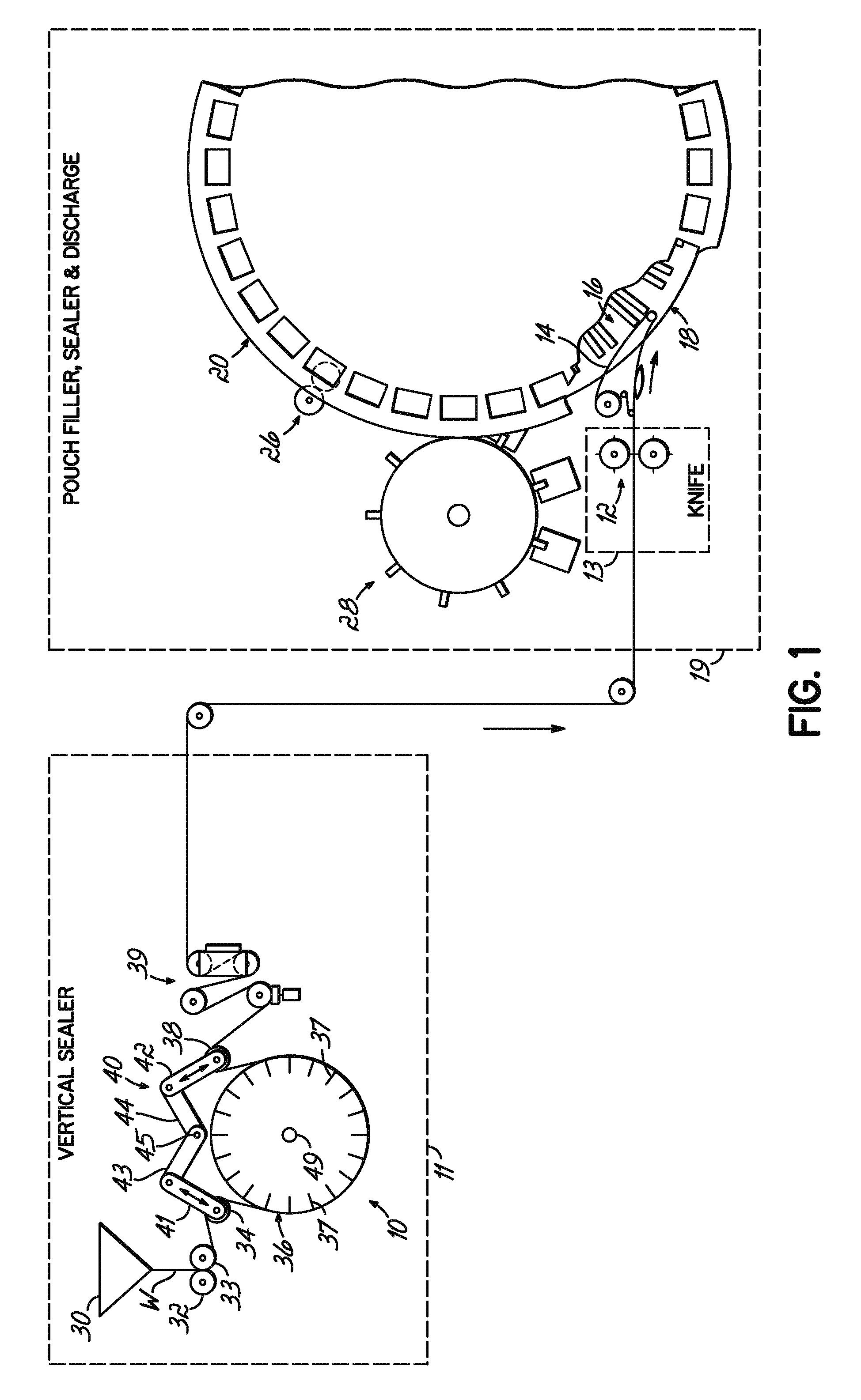
[0102] Turning now to the drawings, it will be appreciated that FIGS. 1-9B illustrate various features of one embodiment of the invention, for example, where the pouches are formed on the vertical sealer wheel then separated before they are introduced to a filler wheel. The separated pouches are thereafter filled, sealed and discharged.

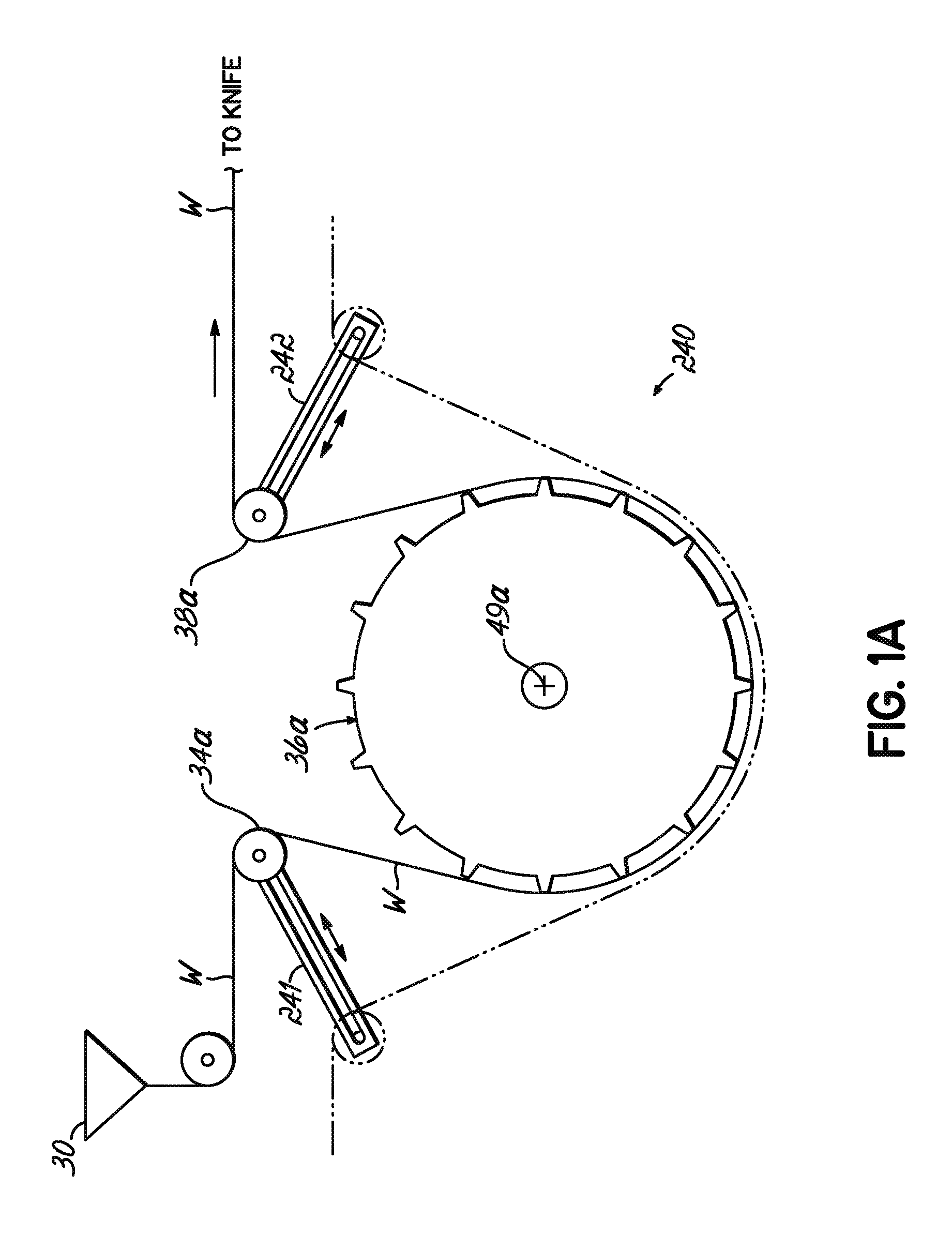
[0103] In another embodiment of the invention, such as shown in FIGS. 11 and 12, the pouches are formed on the vertical sealer wheel, but are introduced to the filler wheel in a pouch train, where the pouches are filled, the tops are sealed, and thereafter the pouches are cut off, one from the other, for discharge.

[0104] Other embodiments of the invention or components of the two embodiments described above are shown in the additional Figures.

[0105] Turning now to FIGS. 1-9B, a first embodiment of the invention will be described. FIG. 1 illustrates the overall layout of the first embodiment of the invention. In FIG. 1, there is shown a vertical sea...


PUM

PropertyMeasurementUnit
Diameteraaaaaaaaaa
Widthaaaaaaaaaa
Areaaaaaaaaaaa

Abstract

An adjustable pouch machine comprises a vertical sealer module forms transverse seals between two plies of a pouch web to partially define a plurality of pouches. Rollers selectively tension and relax the web on the vertically oriented wheel, allowing them to drop away from heated lands on emergency and cycle stops. A filler wheel has a plurality of adjustable gripper units mounted directly thereon for transporting independent separate pouches cut from the pouch web. An adjustable knife is selectively provided with changeable knife hub sets to handle a variety of pouch sizes where a filler wheel alternately first fills and seals pouches in a train. Gear linkage accommodates variation in distance between hubs of different sets. Various embodiments, apparatus and methods are described.

Description

PRIORITY CLAIM [0001] Applicant claims the benefit of the filing date of the U.S. provisional patent application Ser. No. 60 / 763,940 by the same title, filed on Jan. 31, 2006.FIELD OF THE INVENTION [0002] This invention relates to pouch forming, pouch filling and pouch sealing. More particularly, this invention relates to apparatus and methods for performing these operations for a wide range of pouch sizes in an adjustable pouch machine. BACKGROUND OF THE INVENTION [0003] In the past, pouches have been formed, filled and sealed in a variety of ways. Some prior devices operated on an intermittent basis, which is not generally conducive to efficiency where pouches must be formed, filled and sealed at higher rates than intermittent motion machines can effectively produce. [0004] In one prior continuous operation, such as illustrated in U.S. Pat. No. 3,821,873, expressly incorporated herein by reference as if fully set out herein, pouches are formed by folding a pouch web lengthwise, cr...

Claims


Application Information

Patent Timeline
IPC IPC(8): B65B43/04B31B50/64
CPCB65B9/087B65B43/465B65B43/08B65B59/02B31B3/00B65B43/60B31B50/12B31B50/32B31B2100/00B65B59/003Y10T83/04Y10T83/0515Y10T83/4705Y10T83/9396B65B1/363B65B39/145B65B43/04B65B61/28B31B50/80
Inventor PAUNESKU, SIMARACK, DANIEL J.WINTRING, JEFFREY D.ROTH, RICHARD A.
Owner R A JONES
Why Eureka
Try Eureka