Biological scrubber odor control system and method

a technology of biological scrubber and control system, applied in the field of control system and method, can solve the problems of high operating and maintenance cost, hydrogen sulfide is noted for its toxicity and its capacity for corroding materials, and the primary cause of odor is hydrogen sulfid

Active Publication Date: 2007-08-09
EVOQUA WATER TECH LLC
View PDF9 Cites 34 Cited by
  • Summary
  • Abstract
  • Description
  • Claims
  • Application Information

AI Technical Summary

Benefits of technology

[0014] In accordance with one or more embodiments, the invention relates to a method for controlling odor in a gas stream. The method can comprise acts of providing a scrubber column, establishing a first liquid circuit for a predetermined period of time from a scrubber sump to a first biologically active stage of the scrubber

Problems solved by technology

Significant design problems are associated with the removal of unwanted odorous constituents from effluent gas streams when public health and aesthetic considerations make it desirable to do so.
For example, in a sewage system environment, a primary cause of odor is hydrogen sulfide.
In addition to the unpleasant odor ass

Method used


Image

  • Biological scrubber odor control system and method
  • Biological scrubber odor control system and method
  • Biological scrubber odor control system and method

Examples


example 1

Performance of an Odor Control System Operated in a First Mode.

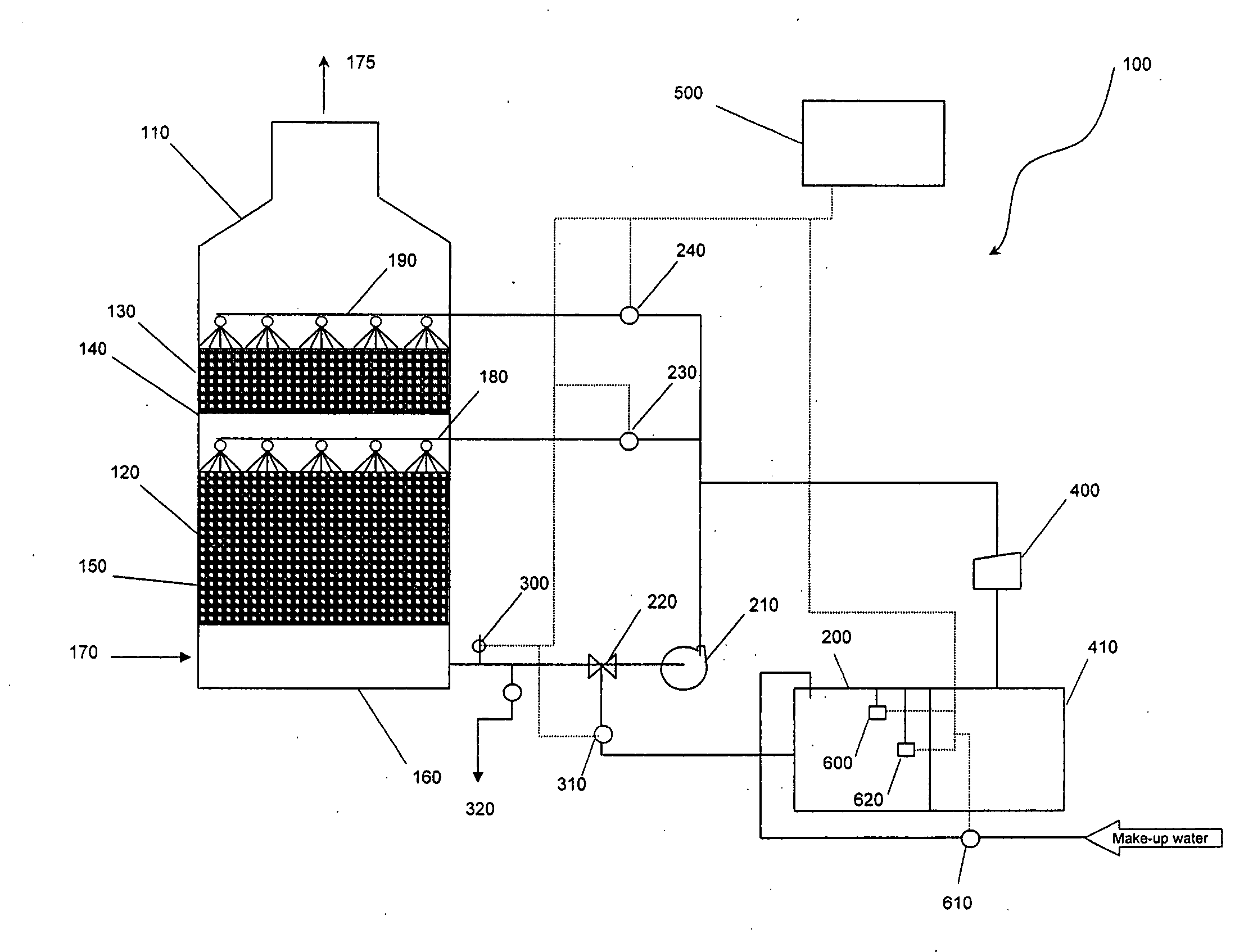
[0083] An odor control system was designed substantially in accordance with one or more embodiments of the invention as described above and illustrated in FIG. 1. In this example, the odor control system 100 was operated over the course of a one week period in the second mode of operation discussed above. A liquid circuit was established fluidly connecting the scrubber sump 160 to the second scrubber stage 130, substantially in accordance with the third liquid circuit described above and illustrated in FIG. 4. During operation, irrigation fluid from the scrubber sump 160 was recycled to the second scrubber stage 130, delivering acidic byproducts to both scrubber stages 120, 130. Scrubber column 10 operated virtually as a recirculating single-stage scrubber, maintaining both scrubber stages 120, 130 at a low pH level conducive to the growth of sulfur-oxidizing bacteria. Makeup water was added to maintain a pH level of ab...

example 2

Performance of an Odor Control System Operated in a Second Mode.

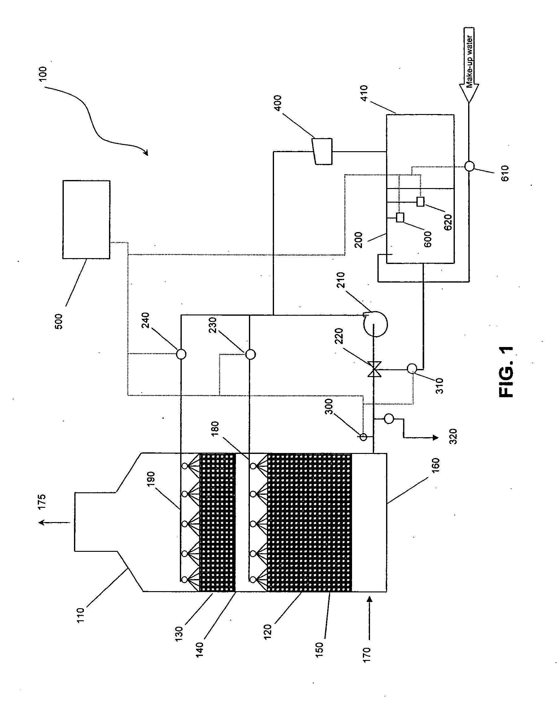
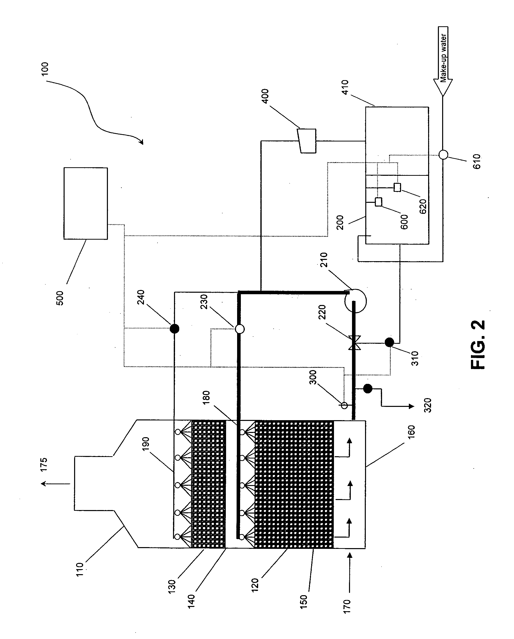
[0085] This prophetic example describes the odor control system as provided in Example 1, but operated substantially in accordance with the first mode of operation described above. Irrigation fluid is recycled along a first liquid circuit, as illustrated in FIG. 2, from scrubber sump 160 to the first scrubber stage 120 for 57 minutes out of every hour, and fresh irrigation fluid is delivered along a second liquid circuit, as illustrated in FIG. 3, from irrigation source 200 to the second scrubber stage 130 for the remaining 3 minutes out of every hour. Thus, the first scrubber stage 120 is maintained at a lower pH level conducive to the growth of, for example, sulfur-oxidizing bacteria, while the second scrubber stage 130 is maintained at a higher pH level conducive to the growth of a wider range of bacteria. Odor control system 100 would be efficient in removing a variety of odorous constituents from process gas, with...


PUM

PropertyMeasurementUnit
Temperatureaaaaaaaaaa
Volumeaaaaaaaaaa
Lengthaaaaaaaaaa

Abstract

A system and method for the purification and biodeodorizing of a gas are disclosed. The system is highly adaptable and capable of operating in a variety of modes to tailor performance of the system to specific odor control applications. The scrubber stages of the system may each be maintained at different conditions to selectively promote bacterial activity that targets a variety of odorous constituents. The pH level of the irrigation fluid provided to each scrubber stage may be controlled.

Description

BACKGROUND OF THE INVENTION [0001] 1. Field of the Invention [0002] The present invention relates, generally, to control systems and methods for removing undesirable constituents from fluid streams. More specifically, the invention relates to a biological treatment system and method for cleansing and deodorizing gas effluents by reducing the concentration of odorous constituents present. [0003] 2. Description of Related Art [0004] Increased industrialization and population growth in urban settings over the past several decades have presented important environmental concerns. Significant design problems are associated with the removal of unwanted odorous constituents from effluent gas streams when public health and aesthetic considerations make it desirable to do so. [0005] Various techniques have been developed in response to the need for removal of odorous constituents from effluent gas streams. As a general rule, an effective technique should be tailored to the particular compound...

Claims


Application Information

Patent Timeline
IPC IPC(8): B01D50/00B01D53/48B01D59/50
CPCB01D53/84B01D2257/30B01D2257/304Y10S423/05B01D2257/406Y10S423/17B01D2257/40Y02A50/20
Inventor PARKER, RICHARD D.DAVIS, ERIC C.JAIN, ROOP C.
Owner EVOQUA WATER TECH LLC
Why Eureka
Try Eureka