Thin film tuning-fork type inflection resonator and electric signal processing element

a tuning fork type, inflection resonator technology, applied in piezoelectric/electrostrictive/magnetostrictive devices, piezoelectric/electrostriction/magnetostriction machines, electrical equipment, etc., can solve the problem of difficult manufacturing of resonators by the above manufacturing process, limited typical manufacturing methods, and reduced subject resonators. problem, to achieve the effect of small manufacturing deviation and easy integration of resonators with electronically active elements

Inactive Publication Date: 2007-08-09
HITACHI LTD
View PDF5 Cites 15 Cited by
  • Summary
  • Abstract
  • Description
  • Claims
  • Application Information

AI Technical Summary

Benefits of technology

[0030]According to one aspect of the present invention, therefore, it is possible to provide a resonator with a small range of frequency variations using a thin film piezoelectric material.
[0031]According to another aspect of the present invention, it is possible to provide a compact resonator using a thin film piezoelectric material to make it easier to integrate the resonator with electronically active elements.
[0032]According to still another aspect of the present invention, it is possible to provide an integrated circuit device with a small manufacturing deviation, in which a compact resonator that uses a thin piezoelectric material is integrated with electronically active elements.

Problems solved by technology

However, the above described conventional quartz tuning-fork type resonator includes the following problems.
Because the above manufacturing method is employed for rock quartzes, the conventional typical manufacturing method is limited to miniaturize rock quartzes.
In addition, when a higher specific vibration frequency is used, the subject resonator must be reduced in size, and therefore it is difficult to manufacture the resonator by the above manufacturing process.
Furthermore, the bandwidth of the resonator becomes narrow and the specific vibration frequency process variation becomes large.

Method used


Image

  • Thin film tuning-fork type inflection resonator and electric signal processing element
  • Thin film tuning-fork type inflection resonator and electric signal processing element
  • Thin film tuning-fork type inflection resonator and electric signal processing element

Examples


first embodiment

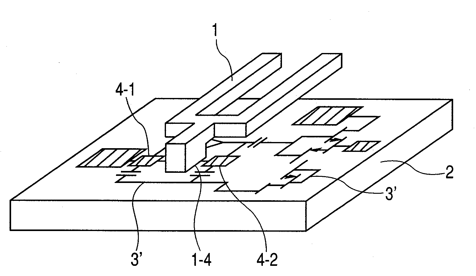
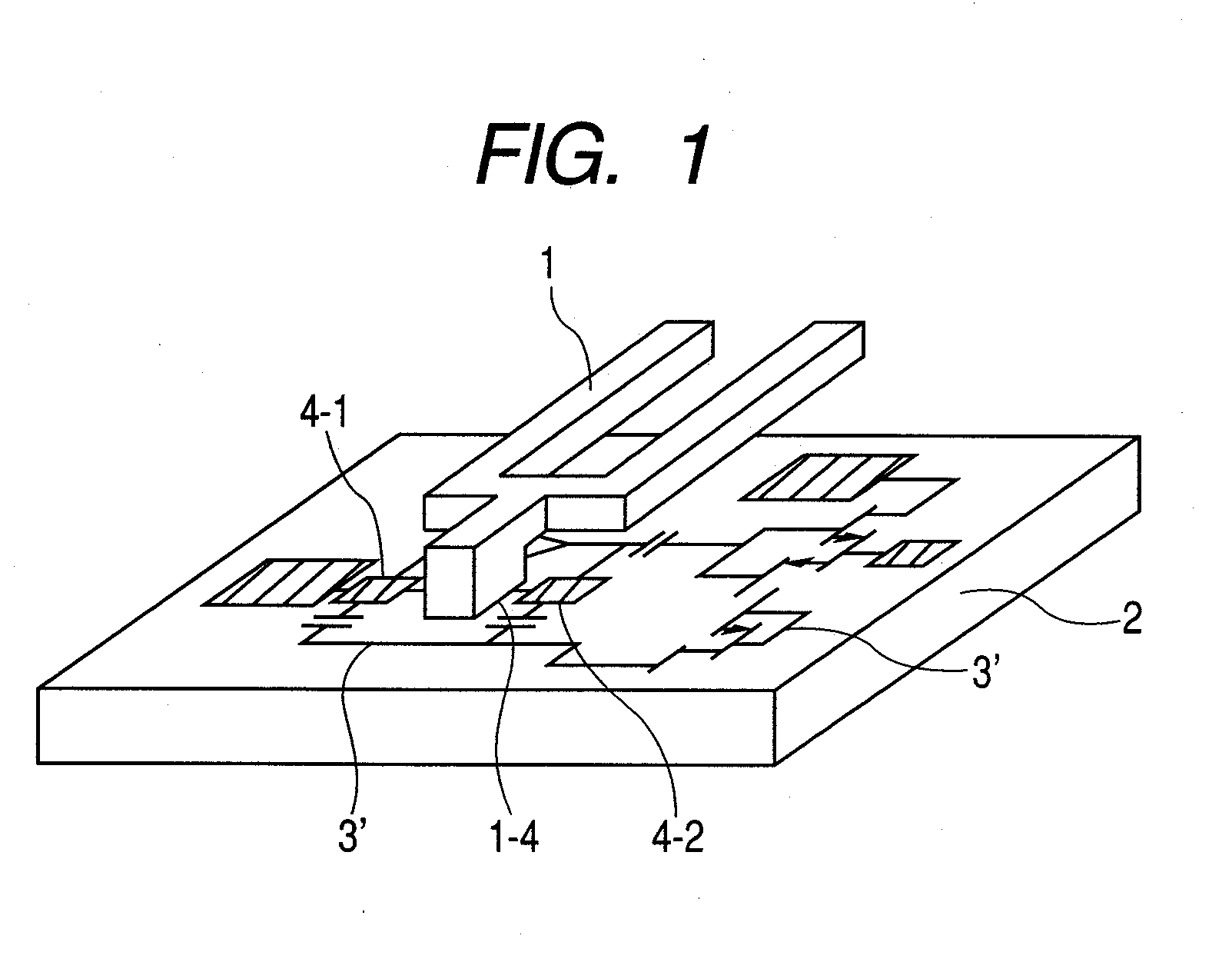
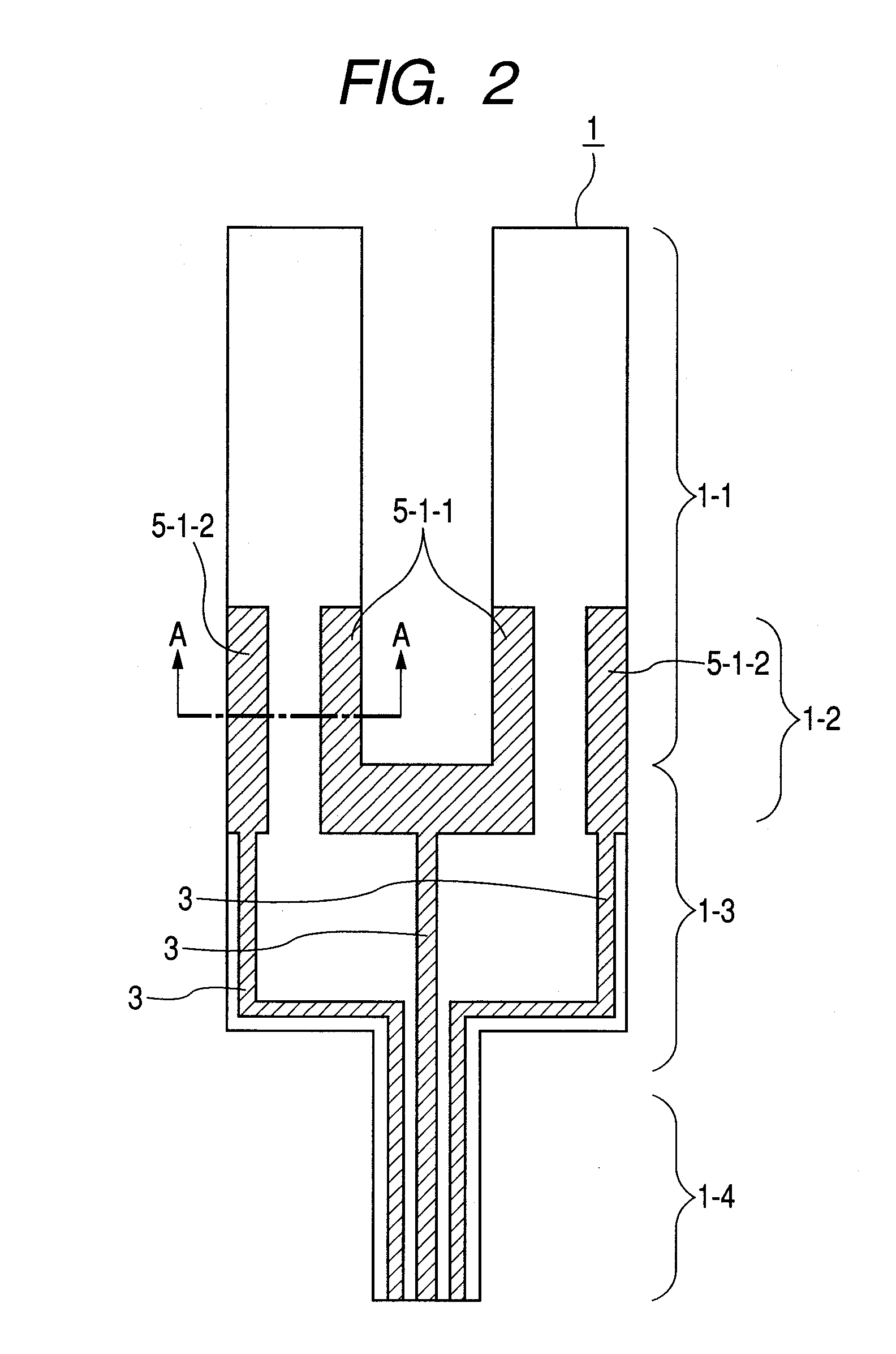
[0063]FIG. 1 is a perspective view of a thin film tuning-fork type resonator according to the present invention. FIGS. 2 and 3 are top and bottom drawings of the resonator, respectively. A resonator 1 is provided in parallel to a surface of a silicon substrate 2. The resonator 1 has a tuning fork shape. More concretely, as shown clearly in FIGS. 2 and 3, the resonator 1 comprises a pair of vibrating parts 1-1 (width; 30 um, length; 50 um respectively); a pair of excitation parts 1-2 for exciting the vibrating parts; a pedestal part 1-3 for separating vibration energy accumulated in both vibrating parts 1-1 and excitation parts 1-2 from a supporting part 1-4; and a supporting part 1-4 for fixing the resonator 1 to the silicon substrate 2 physically. The exciting parts 1-2 are formed doubly in both of the vibrating parts 1-1 and part of the pedestal part 1-3 so as to function as an exciting part.

[0064]Furthermore, an electric lead line 3 is formed in the supporting part 1-4 to connect...

second embodiment

[0079]FIGS. 8 and 9 show still another preferred embodiment of the resonator described in the present invention. FIG. 8 shows a top view of the resonator and FIG. 9 shows a cross-sectional view of the resonator taken along a line A-A. In FIGS. 8 and 9, the same numerals are used for the same parts of those shown in FIGS. 2 and 5. Reference numeral 5-2 denotes a lower electrode. In this embodiment, the lower electrode 5-2 of the resonator is not connected to any of the upper electrodes 5-1. The lower electrode 5-2 shown in FIGS. 8 and 9 is formed as a floating electrode, or an electrode connected to the ground.

[0080]On the other hand, in the case of the resonator shown in each of FIGS. 2 and 3, 5-1-1 and 5-2-1 are connected to the port 4-1 and 5-1-2 and 5-2-2 are connected to the port 4-2. In the first embodiment of the present invention, however, 5-1-1 is connected to the port 4-1 and 5-1-2 is connected to the port 4-2. The floating electrode 5-2 is given a potential between 5-1-1 a...


PUM


Abstract

A compact resonator has a wide bandwidth and a small variation of the specific vibration frequency. The resonator is a thin film tuning-fork type inflection resonator in which a thin film made of a piezoelectric material is formed on a substrate on which a lower electrode is formed, and an upper electrode is formed on the piezoelectric thin film.

Description

CLAIM OF PRIORITY[0001]The present application claims priority from Japanese application JP 2006-028230 filed on Feb. 6, 2006, the content of which is hereby incorporated by reference into this application.FIELD OF THE INVENTION[0002]The present invention relates to a thin film tuning-fork type resonator formed by a film manufacturing method and employed for generating reference frequency signals for a microcomputer. Furthermore, the present invention relates to an electric signal processing element that uses the thin film tuning-fork type resonator.BACKGROUND OF THE INVENTION[0003]A conventional quartz tuning-fork type resonator is manufactured by cutting a rock quartz, generated with an autoclave or the like, into a thin slice, forming the thin-slice quartz into a tuning-fork shape by a lithography process and quartz-specific anisotropic etching, arranging the electrodes on both sides of the thin quartz formed into the tuning-fork shape, and then mounting the thin quartz on the sy...

Claims


Application Information

Patent Timeline
Patent Type & Authority Applications(United States)
IPC IPC(8): H03H9/21
CPCH03H2003/026H03H9/21
Inventor ISOBE, ATSUSHISHIBAGAKI, NOBUHIKOASAI, KENGOMATSUMOTO, HISANORI
Owner HITACHI LTD
Why Eureka
Try Eureka