Turbocharger bearing assembly

a bearing assembly and turbocharger technology, applied in the direction of bearing unit rigid support, machines/engines, mechanical equipment, etc., can solve the problems of assembly step reduction, and achieve the effect of reducing the number of assembly steps, simple configuration, and reducing assembly steps

Inactive Publication Date: 2007-08-09
JTEKT CORP
View PDF14 Cites 32 Cited by
  • Summary
  • Abstract
  • Description
  • Claims
  • Application Information

AI Technical Summary

Benefits of technology

[0007] According to the above turbocharger bearing assembly, a bearing unit including two bearings is constituted by assembling the respective pairs of outer rings and sleeves to the single cylindrical inner ring. Thus, the number of assembly steps is reduced. The sleeves interposed between the outer rings are engaged with the housing and with the outer rings, thereby preventing the outer rings from rotating relative to the housing. Furthermore, the outer rings need not be formed in a complicated configuration for implementing therein a function of a spring seat, because the pair of sleeves, separate from the outer rings, are interposed between the outer rings, while the spring is interposed between these sleeves. Therefore, the outer ring has a simple configuration, permitting a general-purpose outer ring to be applied to the bearing assembly.
[0008] According to the above turbocharger bearing assembly, it is preferred that the sleeve is formed from a resin material and that the sleeve and the outer ring are integrally formed. For instance, an outer ring formed from a steel material may be previously set in as part of a mold, which may be filled with the resin material. The outer ring and the sleeve may be integrally formed by taking this procedure, so that these components may be handled as a single part. Thus, the assembly work for the turbocharger bearing assembly involves a reduced number of components, resulting in the reduction of the assembly steps.
[0009] According to the above turbocharger bearing assembly, it is preferred that an annularly notched step portion is formed on an inner periphery of the sleeve at an inside end thereof with respect to the axial direction of the rotary shaft. In this case, the length of the spring for applying the preload is increased by a depth of the recess, so that the spring has a smaller spring constant. Thus, the spring is adapted to apply the proper preload to the bearings in a more stable manner.
[0010] According to the above turbocharger bearing assembly, the inner periphery of the sleeve and the outer periphery of the inner ring may also cooperate to constitute a labyrinth seal having a gap of 0.5 mm or less. In a case where the bearing assembly is provided with grease lubrication, this constitution negates the need for providing a seal member on an inner side with respect to the rolling elements. Hence, the turbocharger bearing assembly may be manufactured at low cost.
[0011] According to the above turbocharger bearing assembly, it is preferred that the inner ring is formed with a recess on the inner periphery thereof for defining a gap between itself and the rotary shaft, the recess extended across a required axial range. This is effective to reduce a pressing force for press-fitting the inner ring on the rotary shaft, obviating indentation produced by press-fitting the inner ring on the rotary shaft. In this case, an inside diameter of the inner ring and an outside diameter of the rotary shaft may be adjusted such that the press-fitting force is smaller than an indentation producing load.

Problems solved by technology

Thus, the assembly work for the turbocharger bearing assembly involves a reduced number of components, resulting in the reduction of the assembly steps.

Method used


Image

  • Turbocharger bearing assembly
  • Turbocharger bearing assembly
  • Turbocharger bearing assembly

Examples


Embodiment Construction

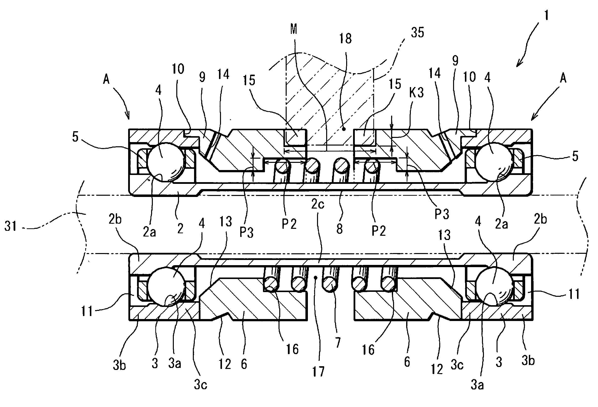
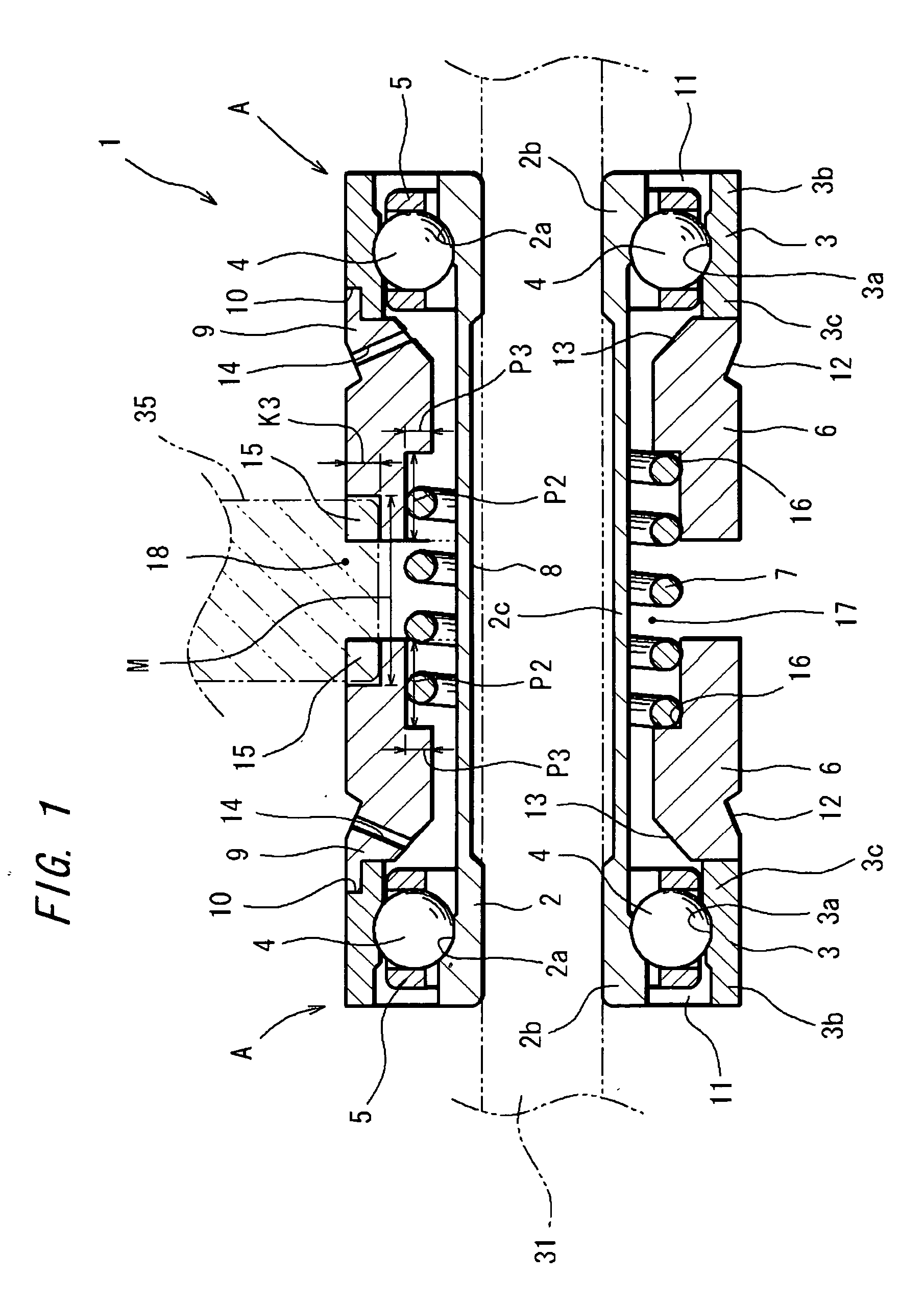
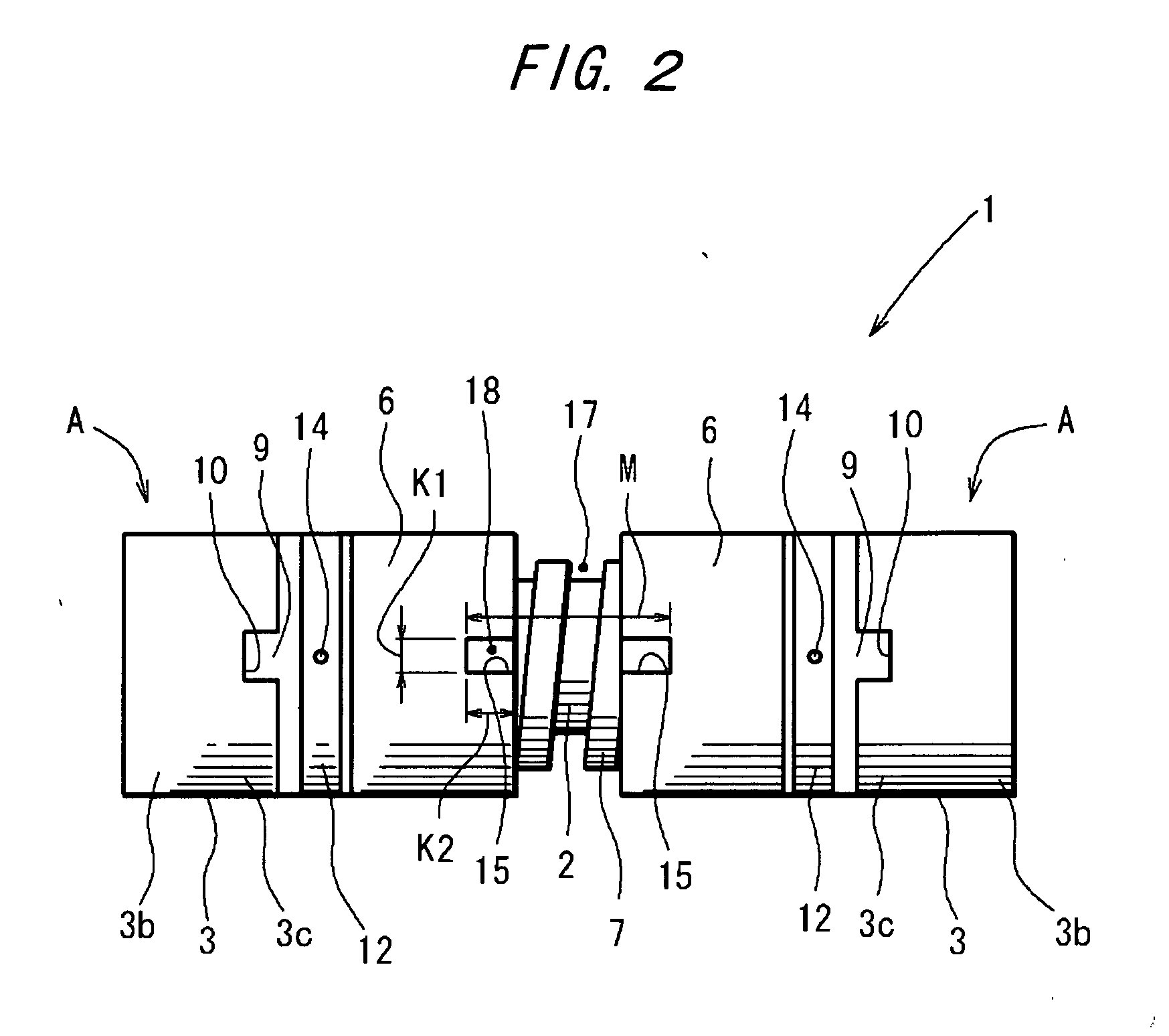
[0016] Preferred embodiments of the invention will hereinbelow be described with reference to the accompanying drawings. FIG.1 is a sectional view showing a turbocharger bearing assembly 1 according to one embodiment of the invention. FIG. 2 is a plan view of the bearing. FIG.3 schematically shows an arrangement of a turbocharger T assembled with the turbocharger bearing assembly 1. The turbocharger T utilizes exhaust gas through an exhaust-gas flow path 30 for rotating a turbine 32 fixed to one end (the right-hand side as seen in FIG.3) of a rotary shaft 31. The rotation of the rotary shaft 31 is transmitted to an impeller 33 fixed to the other end (the left-hand side as seen in FIG.3) of the rotary shaft 31. The impeller 33 compresses intake air in an intake air path 37. Thus, the compressed air along with a fuel such as gasoline or light oil is fed into a cylinder of an engine. The rotary shaft 31 of such a turbocharger T is rotated at such a high speed on the order of tens of th...


PUM


Abstract

A turbocharger bearing assembly is disposed in a housing for rotatably supporting an intermediate portion of a rotary shaft of a turbocharger. A pair of outer rings formed with outer raceways are mounted to opposite ends of a substantially cylindrical inner ring formed with inner raceways, thereby constituting a bearing unit including two angular bearings. Thus, the number of assembly steps is reduced to facilitate an assembly work. A pair of sleeves are inserted in a gap defined between the outer rings. The sleeve is formed with an engaging portion on an outer periphery thereof for restricting its rotation relative to the housing and the outer ring. This makes it easy to position the bearing in the housing.

Description

TECHNICAL FIELD [0001] The present invention relates to a bearing assembly for rotatably supporting a rotary shaft of an automotive turbocharger. BACKGROUND ART [0002] In response to a recent demand for fuel-efficient, low-emission automotive vehicles, an increasing number of automotive vehicles are equipped with turbochargers. The turbocharger includes a rolling bearing (hereinafter, referred to as “bearing”) which is disposed in a housing for rotatably supporting the rotary shaft of the turbocharger. Such a bearing operates in an extremely severe environment of ultra-high speed rotation, extremely great acceleration or deceleration and ultra-high temperatures and besides, is required of high rotational accuracies. It is therefore essential to apply a proper preload to the bearing. This need is properly satisfied by applying a constant preload to the bearing. In a prior-art technique, a spacer and a spring for applying the preload are assembled between two bearings each including a...

Claims


Application Information

Patent Timeline
Patent Type & Authority Applications(United States)
IPC IPC(8): F16C33/66F02B39/00F01D25/16F02C7/06F16C19/18F16C25/08F16C33/58F16C33/60F16C33/62F16C33/80
CPCF01D25/16F02C7/06F16C19/184F16C35/067F16C27/04F05D2220/40F16C2360/24F16C25/083F16C2226/50
Inventor UMEKAWA, TAKAHIRO
Owner JTEKT CORP
Why Eureka
Try Eureka