Method for recovering noble metals from metallic carrier catalytic device

Inactive Publication Date: 2007-08-09
ISHIFUKU METAL IND CO LTD
View PDF1 Cites 20 Cited by
  • Summary
  • Abstract
  • Description
  • Claims
  • Application Information

AI Technical Summary

Benefits of technology

[0007] The main objective of this invention is to provide a method for efficiently separating and recovering a wash coat which supports noble metal-containing catalytic component, from a metallic carri

Problems solved by technology

When this acid dissolution method is applied to a metallic carrier catalytic device, however, a large amount of acid is required for the dissolution of metallic carrier, and, furthermore, it is difficult to effectively separate noble metals from the resultant solution.
In this method, howe

Method used


Image

  • Method for recovering noble metals from metallic carrier catalytic device
  • Method for recovering noble metals from metallic carrier catalytic device

Examples


referential example 1

[0025] A heat-resistant stainless steel honeycomb body having a diameter of 900 mm and a height of 1260 mm (hereinafter referred to as metallic carrier; volume: 800 cc) was coated with 140 g of activated alumina, was burned, and was then made to support 0.3 g of platinum (Pt), 2.3 g of palladium (Pd) and 0.3 g of rhodium (Rh) per one metallic carrier, and, thus, a metallic carrier catalytic device was manufactured.

example 1

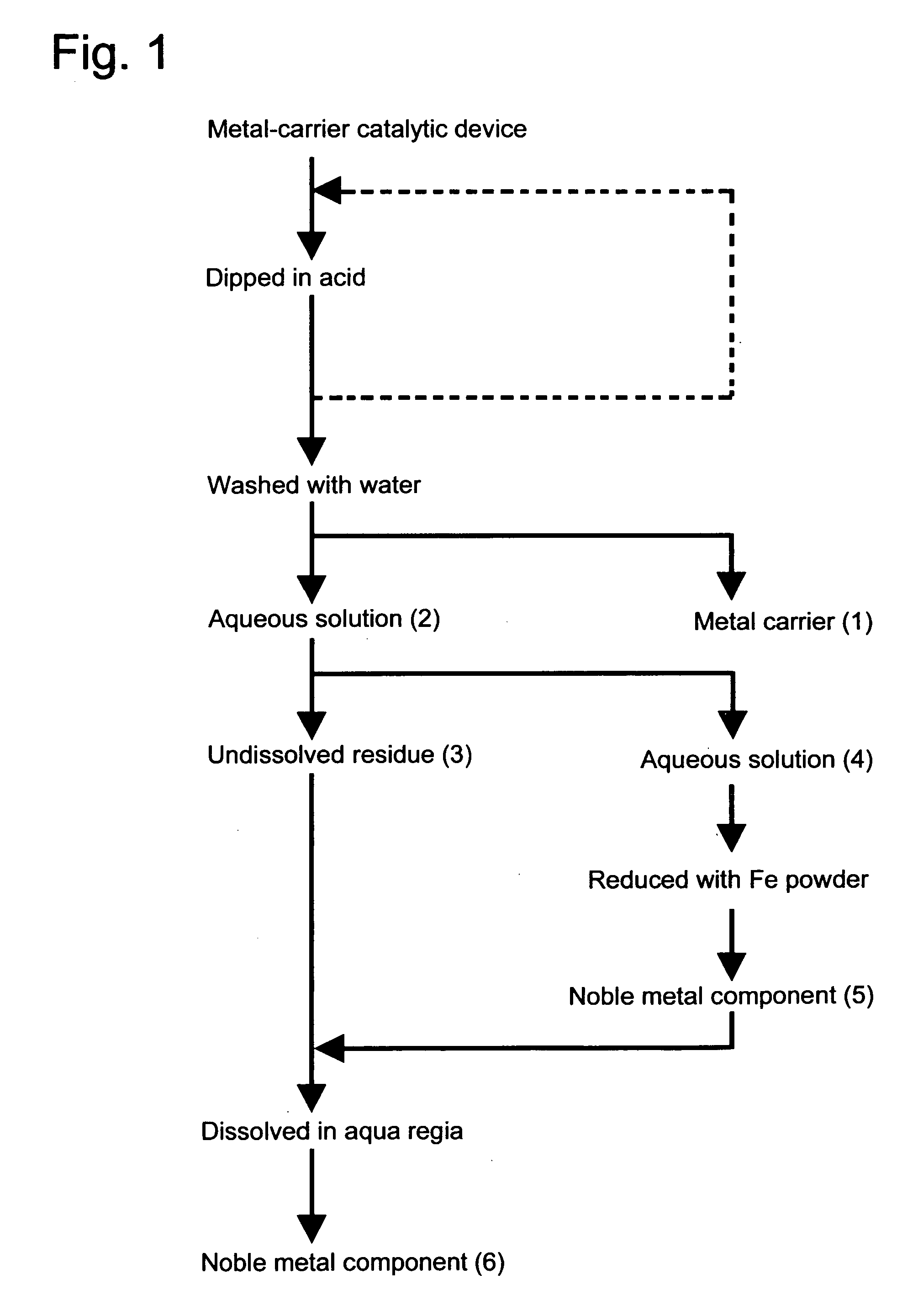
[0026] In accordance .with the flow sheet as shown in FIG. 1, the metallic carrier catalytic device as manufactured in Referential Example 1 was dipped in an aqueous solution which contained 20% by weight of sulfuric acid and 2% by weight of nitric acid, and was thus treated at 80° C. for five hours. After left to cool down, the metallic carrier (1) was taken from said aqueous solution, and was washed with water. Thus obtained wash liquid and the above-mentioned aqueous solution were put together to give an aqueous solution (2) which contained undissolved residue. The recovered metallic carrier had the same appearance as before coated with activated alumina, and showed no sign of dissolution at all.

[0027] Aqueous solution (2) was separated, by filtration, into undissolved residue (3) and aqueous solution (4). Aqueous solution (4) was subjected to a reduction treatment by the addition of 10 g of iron (Fe) powder, and, thus, noble metal (Pt, Pd, Rh) component (5) was deposited and re...

example 2

[0028] In accordance with the flow sheet as shown in FIG. 1, the metallic carrier catalytic device as manufactured in Referential Example 1 was dipped in an aqueous solution which contained 20% by weight of sulfuric acid and 2% by weight of nitric acid, and was thus treated at 80° C. for five hours. Metallic carrier (1) was then taken from said aqueous solution, and was subsequently dipped in a newly prepared aqueous solution which contained 20% by weight of sulfuric acid and 2% by weight of nitric acid, and was thus treated again at 80° C. for five hours. After left to cool down, the metallic carrier was washed with water. Thus obtained wash liquid and the above-mentioned aqueous solution were put together to give an aqueous solution (2) which contained undissolved residue. The recovered metallic carrier had the same appearance as before coated with activated alumina, and showed no sign of dissolution at all.

[0029] Aqueous solution (2) was separated, by filtration, into undissolve...


PUM

PropertyMeasurementUnit
Temperatureaaaaaaaaaa

Abstract

This invention provides a method for efficiently separating and recovering a wash coat which supports noble metal-containing catalytic component from a metallic carrier of a spent metallic carrier catalytic device for such purposes as the purification of exhaust gas from internal combustion engine, without substantially crushing or dissolving said metallic carrier, which method comprises subjecting a metallic carrier catalytic device which is composed of a metallic carrier having a wash coat provided thereon and a noble metal-containing catalytic component which is supported on the wash coat to a treatment with an aqueous solution of mixed acid which contains sulfuric acid and nitric acid.

Description

TECHNICAL FIELD [0001] This invention relates to a method for separating and recovering a wash coat which supports noble metal-containing catalytic component, from a metallic carrier of a spent metallic carrier catalytic device, and also to a method for recovering noble metals. BACKGROUND ART [0002] As examples of carrier for carrying a catalyst of a catalytic device which is used for purifying exhaust gas from internal combustion engine, there are included ceramic carrier and metallic carrier. [0003] For the purpose of recovering noble metals from a ceramic carrier catalytic device, there is generally employed acid dissolution with use of hydrochloric acid, aqua regia, and the like. When this acid dissolution method is applied to a metallic carrier catalytic device, however, a large amount of acid is required for the dissolution of metallic carrier, and, furthermore, it is difficult to effectively separate noble metals from the resultant solution. [0004] For this reason, various pr...

Claims


Application Information

Patent Timeline
IPC IPC(8): C01G55/00B01J23/46B01J37/02B01J38/00B01J38/60C22B3/06C22B3/08C22B3/46
CPCB01J23/464B01J37/0225B01J38/60C22B11/048C22B3/08C22B3/46C22B3/065Y02P10/20
Inventor NAKATSU, SHIGERUYOKOTA, TOMONAO
Owner ISHIFUKU METAL IND CO LTD
Why Eureka
Try Eureka