Supercharge Your Innovation With Domain-Expert AI Agents!

Anti-backlash planetary gearing for optic rotary joint

a planetary gearing and optic rotary joint technology, applied in the field of anti-backlash mechanism of precision planetary gear systems, can solve the problems of motion loss, noise and vibration, clearance or backlash between the teeth of two gears, etc., and achieve the effect of reducing noise and vibration and increasing the accuracy of kinematic transmission

Active Publication Date: 2007-08-09
PRINCETEL
View PDF5 Cites 20 Cited by
  • Summary
  • Abstract
  • Description
  • Claims
  • Application Information

AI Technical Summary

Benefits of technology

[0014] Another object of the present invention is to increase the accuracy of kinematic transmission and to reduce noise and vibration in a planetary gear train.
[0015] A further object of the preset invention is to provide a very low-profile and compact design of a planetary gear train with 2:1 gear ratio for multi-channel fiber optic rotary joints.

Problems solved by technology

In a gear transmission system, when two gears mesh each other, there is usually a clearance, or backlash between the teeth of two gears due to manufacturing errors and assembly errors.
That would cause a motion loss, or kinematic transmission error and dynamically also cause noise and vibration.
The disadvantages of the anti-backlash twin gear are that the diameter of the twin gear need to be large enough for installing the spring bias apparatus and an open space should be big enough for assembly of further gears.
However, this device is complicated and expensive when compared to simple spring biasing system.

Method used


Image

  • Anti-backlash planetary gearing for optic rotary joint
  • Anti-backlash planetary gearing for optic rotary joint
  • Anti-backlash planetary gearing for optic rotary joint

Examples


Embodiment Construction

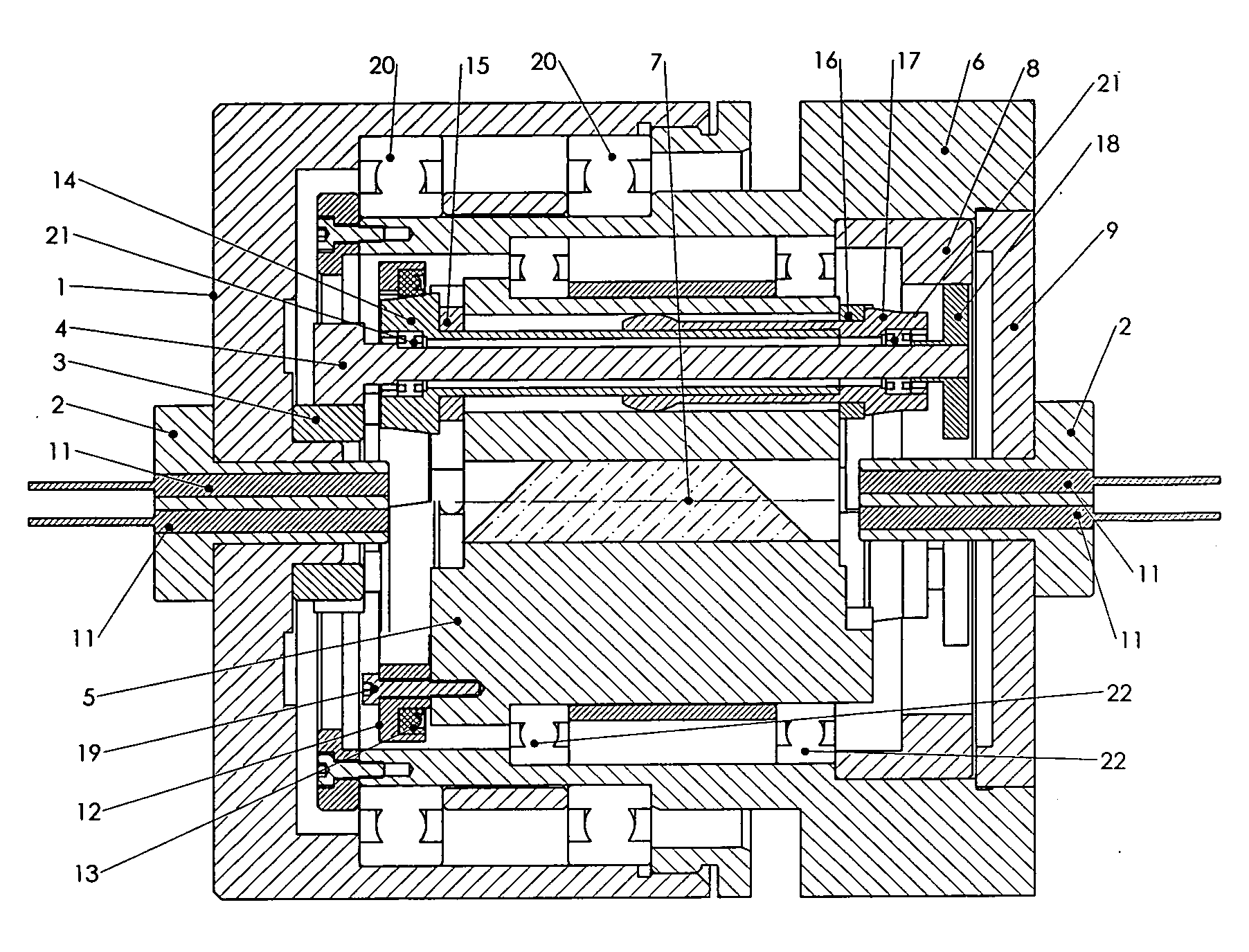
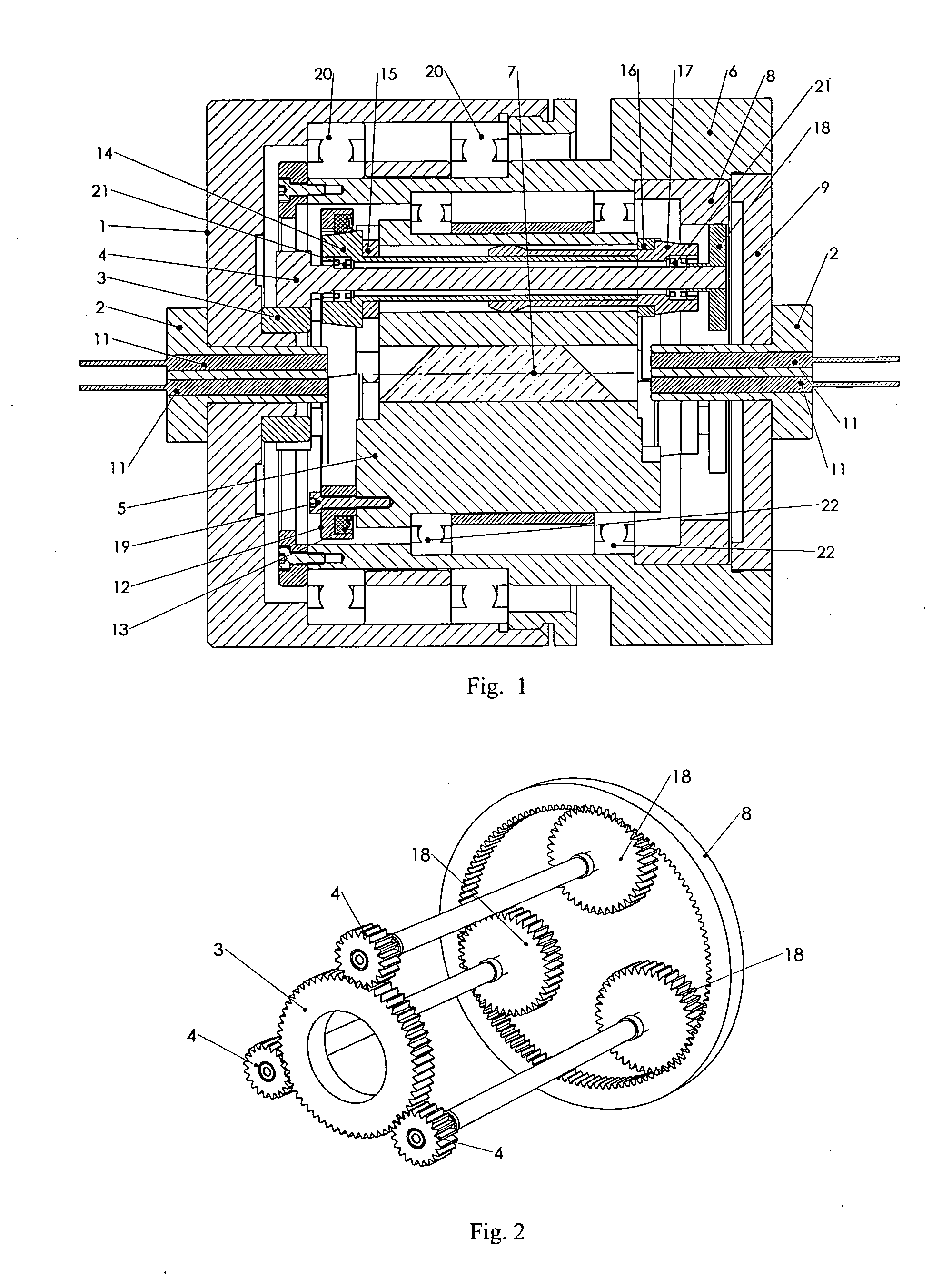
[0021] As shown in FIG. 1, a typical design of a multi-channel fiber optical rotary joint comprises rotor 1, fiber bundles 2, stator 6, Dove prism 7 and prism holder 5. The stationary fiber bundles 2 is mounted along the axis of stator 6 through threaded plate 9. While the rotational fiber bundles 2 is fixed in the central hole of rotor 1. When the rotor 1 rotates, the prism holder 5 should also rotates at half the speed of rotor 1 and in the same rotational direction to ensure the light beam from the collimator 11 of the rotational bundle are transmitted onto the correspondent collimator 11 of the stationary bundle. Vise versa. The 2:1 gear ratio is realized by the planetary gear system which includes sun gear 3, first planet gear 4 (3 pieces), second planet gear 18 (3 pieces), internal gear 8 and carrier 5 (also called prism holder). The first planet gear 4 is coaxially fixed with the second planet gear 18.

[0022] Kinematic joints, i.e., three revolute pairs are constituted throug...


PUM


Abstract

An anti-backlash planetary gear system is disclosed for a multi-channel fiber optic rotary joint which requires 2:1 gear ratio. By adding a local degree of freedom, the planet gear assembly could be tilted relative to the carrier by a spring-loaded annular ring through a spherical feature thus force the three, or more planet gears symmetrically mesh into the sun gear and internal gear. A couple of elastomeric sleeves are introduced into the connection between planet housing and carrier so as to balance the load evenly among the three planet assemblies and to reduce the speed fluctuation of transmitted motion as well as the noise and vibration.

Description

REFERENCES CITED U.S. Patent Documents [0001] U.S. Pat. No. 5,442,721 August 1995 Ames et al. [0002] U.S. Pat. No. 4,189,951 Febuary 1980 Sauter [0003] U.S. Pat. No. 4,072,064 Febuary 1978 Lloyd et al. OTHER PUBLICATIONS [0004]“Fiber Optic Rotary Joints-A Review”, by GLENN F. I. DORSEY. IEEE Trans. Components, Hybrids, and Manufac. Technol., vol. CHMT-5, NO. 1, 1982, PP39. [0005]“Mechanism design, analysis and synthesis, volume 1” by Arther G. Erdman and George N. Sandor. Third Edition. 1997. BACKGROUND OF THE INVENTION [0006] 1. Field of the Invention [0007] The invention is related to epicyclic gear trains, and in particular to anti-backlash mechanism of precision planetary gear systems for the application of multi-channel fiber optical rotary joint in telecommunication industry. [0008] 2. Description of Related Art [0009] In a gear transmission system, when two gears mesh each other, there is usually a clearance, or backlash between the teeth of two gears due to manufacturing err...

Claims


Application Information

Patent Timeline
Patent Type & Authority Applications(United States)
IPC IPC(8): F16H57/08
CPCF16H1/2863G02B6/3604F16H57/12
Inventor ZHANG, HONGZHANG, BOYING B.
Owner PRINCETEL
Features
  • R&D
  • Intellectual Property
  • Life Sciences
  • Materials
  • Tech Scout
  • Unparalleled Data Quality
  • Higher Quality Content
  • 60% Fewer Hallucinations
Learn More