Intradermal injection device

a technology of intradermal injection and injection tube, which is applied in the direction of intravenous device, infusion needle, infusion syringe, etc., can solve the problems of insufficient immune response, difficult to perform intradermal injection, and difficult to perform above-described technique, etc., and achieve good interface and limit leakage

Inactive Publication Date: 2007-08-09
BECTON DICKINSON & CO
View PDF27 Cites 25 Cited by
  • Summary
  • Abstract
  • Description
  • Claims
  • Application Information

AI Technical Summary

Benefits of technology

[0007] In a further aspect of the subject invention, a protrusion is provided on the proximal end of the body of the device which extends proximally from a first surface portion. Preferably, the protrusion is annular and circumscribes the channel. The protrusion aides in the injection process by providing a good interface between the device and the patient's skin, limiting leakage from the injection site during the injection process.

Problems solved by technology

Therefore, a needle cannula that penetrates the skin deeper than about 3 mm has a potential of passing through the dermis layer of the skin, thus making the injection into the subcutaneous region, which may result in an insufficient immune response, especially where the substance to be delivered intradermally has not been indicated for subcutaneous injection.
Also, the needle cannula may penetrate the skin at too shallow a depth to deliver the substance and result in what is commonly known in the art as a “wet injection” due to reflux of the substance from the injection site.
The standard procedure for making an intradermal injection, generally referred to as the Mantoux procedure, is difficult to perform, and successful administration of an intradermal injection using that procedure depends upon experience and technique of the person using the injection device.
The above-described technique is difficult to perform and typically requires the attention of a trained nurse or medical doctor.
Inserting the needle to a depth greater than about 3 mm typically results in a failed intradermal injection because the drug substance being expelled through the cannula will be injected into the subcutaneous tissue of the patient.

Method used


Image

  • Intradermal injection device
  • Intradermal injection device
  • Intradermal injection device

Examples


Embodiment Construction

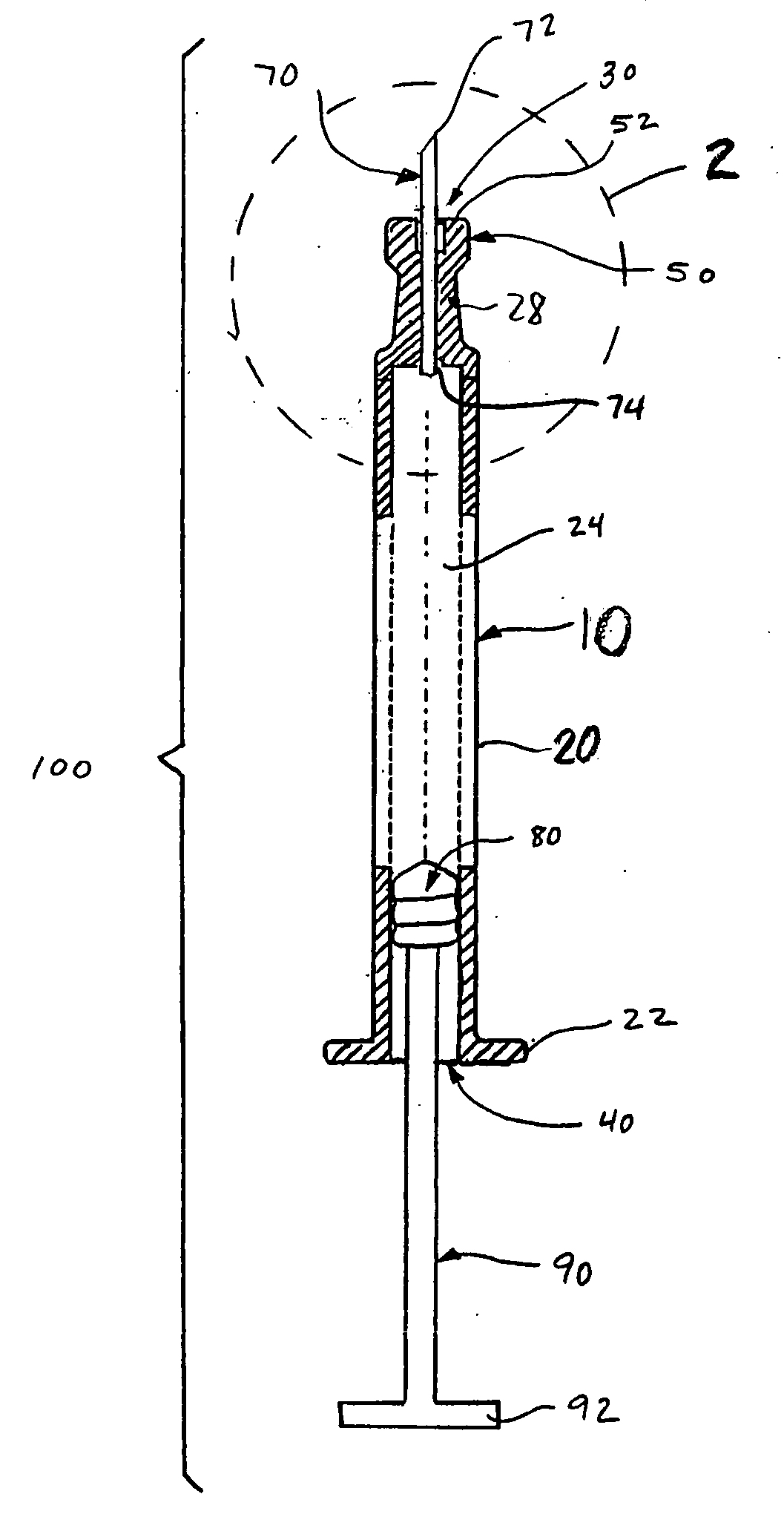
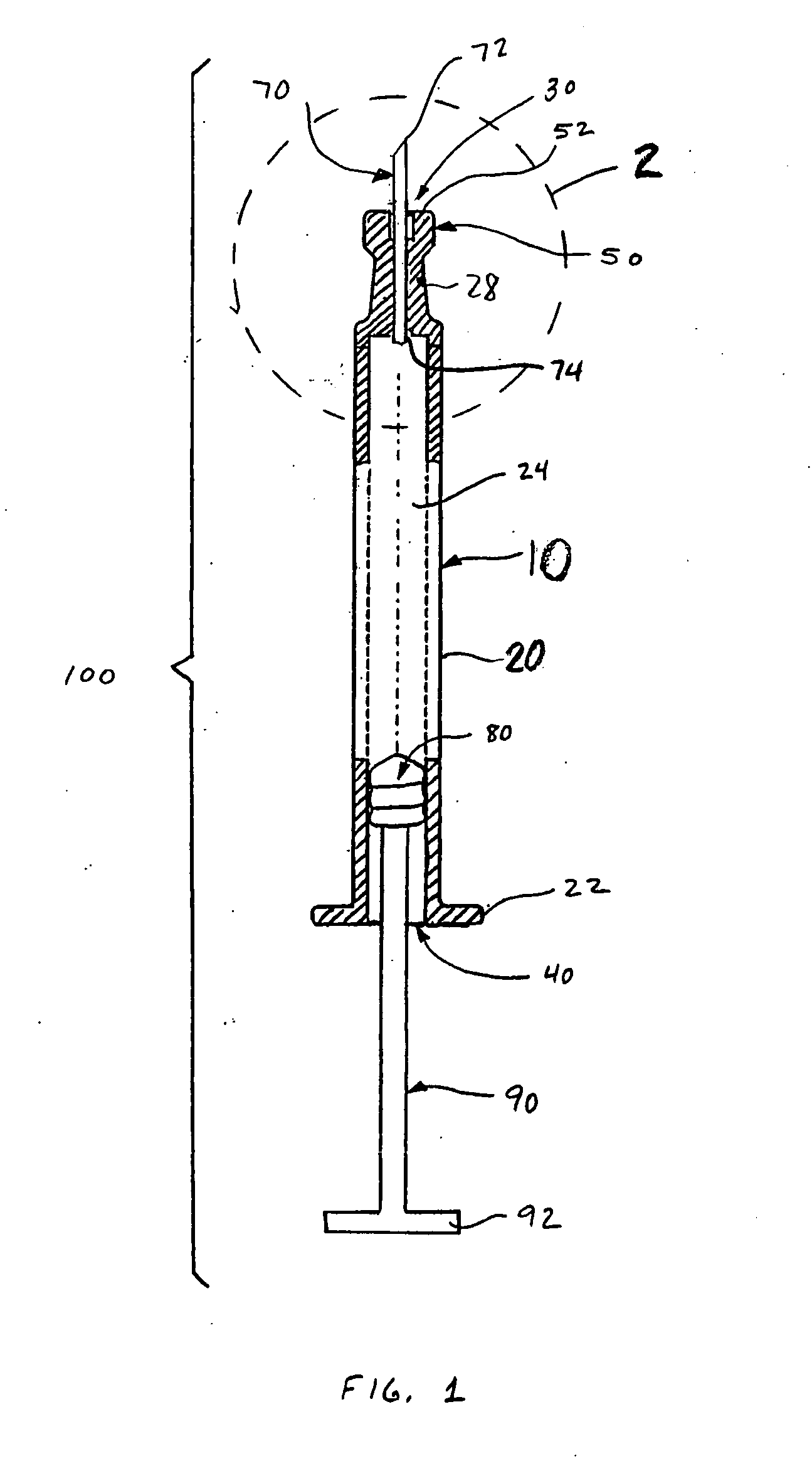
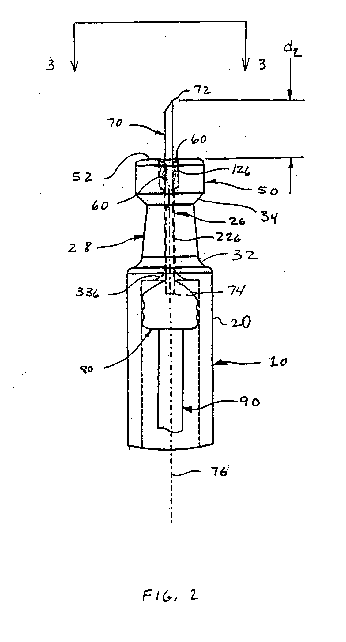
[0021]FIGS. 1-3 depict an intradermal injection device 100 constructed in accordance with an embodiment of the present invention. The injection device 100 is preferably a syringe comprised of a body 10 having a barrel 20, an open distal end 40 with a flange 22, a proximal end 30, and a reservoir 24 defined therebetween. A drug substance may be placed in the reservoir 24 before the injection device 100 is provided to the end user. The injection device 100 also includes a plunger 80 slidingly and sealingly provided within the reservoir 24, and a plunger rod 90 secured to the plunger 80 to facilitate movement of the plunger 80 within the reservoir 24 to effect expulsion of the drug substance therefrom.

[0022] The body 10 narrows near the proximal end 30 to form a neck 28 that supports a limiter 50 defined at the proximal end 30 of the body 10. The neck 28 is preferably tapered, particularly to converge in a distal to proximal direction. A first transition 32 may be provided to accommod...


PUM


Abstract

An intradermal injection device comprising a unitary body having an open distal end and a proximal end having a skin engaging surface defined thereon, a reservoir defined between the proximal and distal ends for accommodating a drug substance, and a channel defined at the proximal end of the unitary body and extending through, and distally from, the skin engaging surface to the reservoir. A needle cannula having a sharpened proximal end and a distal end may be provided in the channel. The needle cannula is secured in the channel with the distal end being in communication with the reservoir and the proximal end of the needle cannula extending from the skin engaging surface a distance in the range of about 0.5 mm to 3.0 mm such that the skin engaging surface limits penetration of the proximal end of the needle cannula to the dermis layer of the skin of a patient.

Description

[0001] This application claims priority to U.S. Provisional Application No. 60 / 498,508, filed Aug. 28, 2003.FIELD OF THE INVENTION [0002] The present invention relates to an intradermal injection device. BACKGROUND [0003] Drug substances may be delivered into a patient's body via injection into the muscle, subcutaneous tissue, or into the epidermis and dermis (also referred to as an intradermal injection). The efficacy of a particular drug substance may change when the drug is delivered intradermally. In some cases, intradermal delivery may be more beneficial to the patient. There is considerable variation in the skin thickness both between individuals and within the same individual at different sites of the body. Generally, the outer skin layer epidermis has a thickness of ranging from 50 to 200 microns, and the dermis, the inner and thicker layer of the skin, has a thickness ranging from 1.5 to 3.5 mm. Therefore, a needle cannula that penetrates the skin deeper than about 3 mm has...

Claims


Application Information

Patent Timeline
Patent Type & Authority Applications(United States)
IPC IPC(8): A61M5/31A61M5/00A61MA61M5/28A61M5/315A61M5/32A61M5/34A61M5/42A61M5/46
CPCA61M5/28A61M5/31511A61M5/321A61M5/343A61M5/425A61M5/46A61M2005/311A61M5/349
Inventor VEDRINE, LIONELALCHAS, PAUL G.HEYMAN, PETER W.BARRELLE, LAURENTKORISCH, MARINA
Owner BECTON DICKINSON & CO
Why Eureka
Try Eureka