Control apparatus and control method for electric vehicle

Active Publication Date: 2007-08-16
TOYOTA JIDOSHA KK +1
View PDF20 Cites 24 Cited by
  • Summary
  • Abstract
  • Description
  • Claims
  • Application Information

AI Technical Summary

Benefits of technology

[0008]The invention provides a control apparatus and a control method for an electric vehicle

Problems solved by technology

However, if the torque output to the drive shaft is rapidly limited when the vehicle slips, the

Method used


Image

  • Control apparatus and control method for electric vehicle
  • Control apparatus and control method for electric vehicle
  • Control apparatus and control method for electric vehicle

Examples


first embodiment

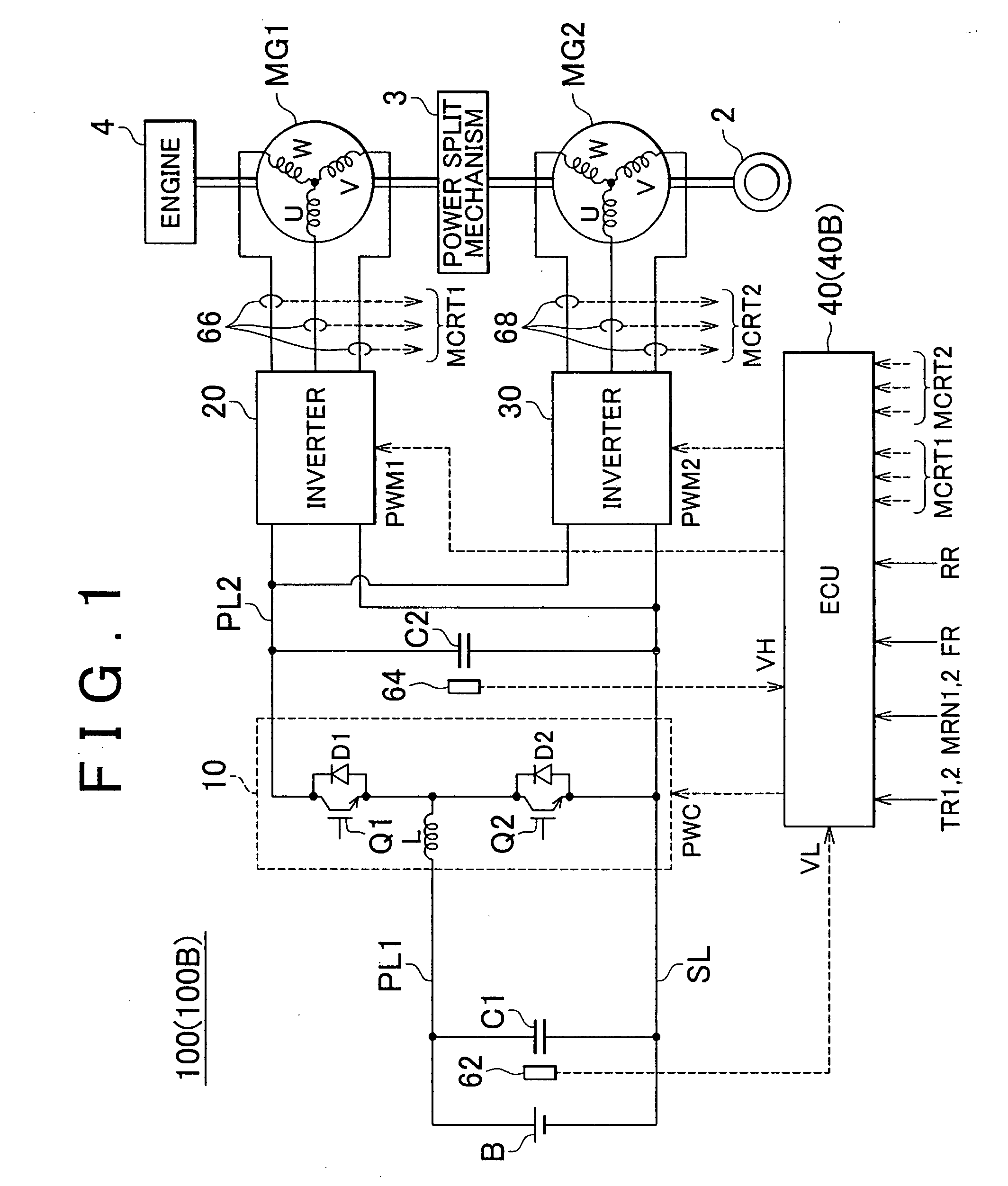
[0047]FIG. 1 is a schematic block diagram of a hybrid vehicle that is an example of an electric vehicle provided with a control apparatus according to the invention. As shown in FIG. 1, the hybrid vehicle 100 includes drive wheels 2, a power split mechanism 3, an engine 4, and motor-generators MG1 and MG2. The hybrid vehicle 100 further includes an electric storage device B, a boost converter 10, inverters 20 and 30, an electronic control unit (hereinafter, referred to as “ECU”) 40, capacitors C1 and C2, power source lines PL1 and PL2, a ground line SL, voltage sensors 62 and 64, and current sensors 66 and 68.

[0048]The power split mechanism 3 is connected to the engine 4 and the motor-generators MG1 and MG2 to distribute power to the engine 4 and the motor-generators MG1 and MG2. For example, a planetary gear mechanism, which includes three rotation shafts of a sun gear, a planetary carrier, and a ring gear, may be used as the power split mechanism 3. The three rotation shafts are c...

second embodiment

[0087]FIG. 5 is a schematic block diagram of a hybrid vehicle that is an example of an electric vehicle provided with a control apparatus according to the invention. As shown in FIG. 5, the configuration of the hybrid vehicle 100A is the same as that of the hybrid vehicle 100 shown in FIG. 1, except that the hybrid vehicle 100A includes an ECU 40A instead of the ECU 40, and further includes an engine ECU 45.

[0088]The engine ECU 45 receives a control signal CTLEG from the ECU 40A. When the control signal CTLEG is activated, the engine ECU 45 controls the engine 4 to reduce the speed of the engine 4. Thus, when the control signal CTLEG is activated, the amount of electric power generated by the motor-generator MG1 using the power supplied from the engine 4 is reduced.

[0089]The ECU 40 determines whether the vehicle is slipping based on the rotation speeds FR and RR, using a method similar to that used by the ECU 40 in the first embodiment. When the ECU 40A determines that the vehicle i...

third embodiment

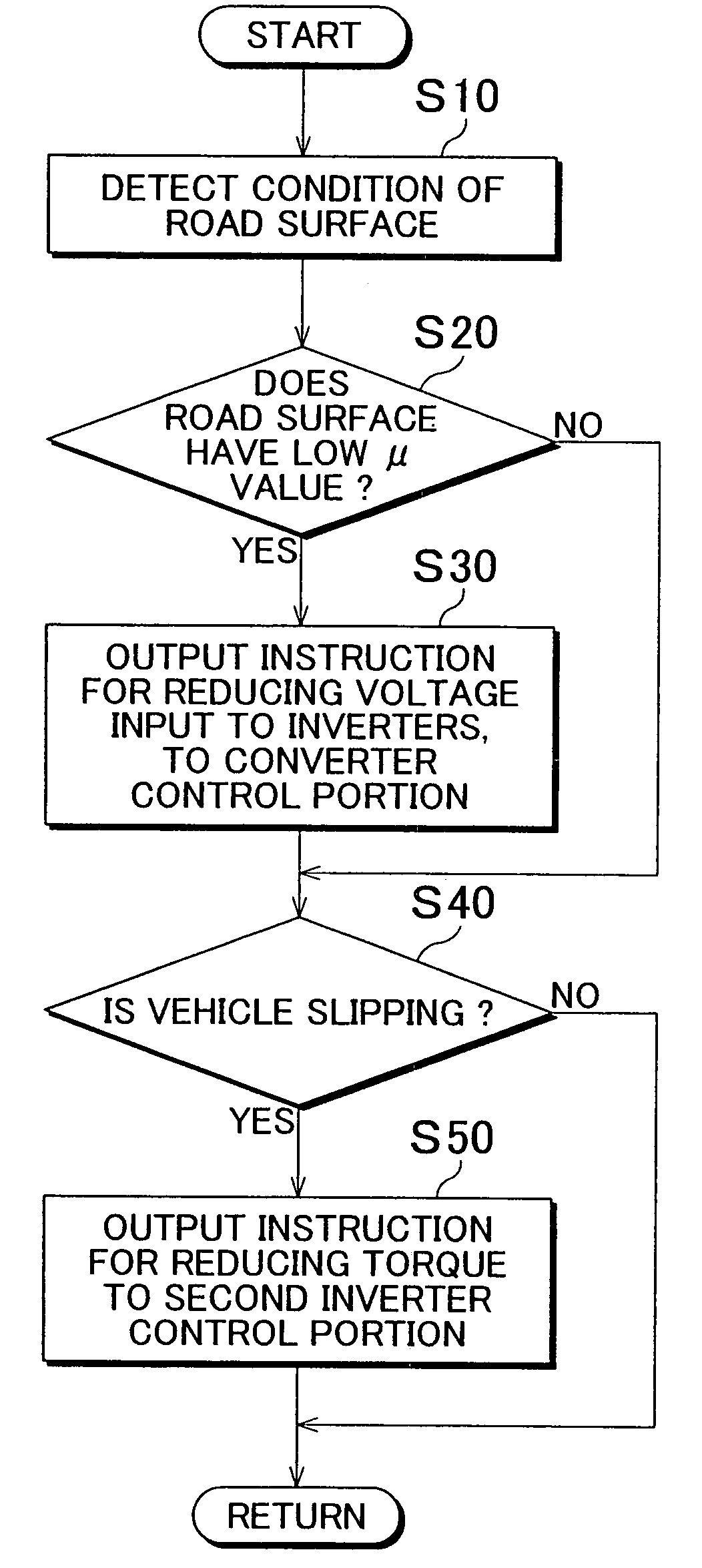
[0110]In a third embodiment, when it is determined that the vehicle is slipping, the torque of the motor-generator MG2 is reduced at a rate that is lower than a rate while no slipping is determined. This prevents a sharp change in the balance between the amount of electric power generated by the motor-generator MG1 and the amount of electric power consumed by the motor-generator MG2, and prevents an excessive voltage VH.

[0111]The configuration of the hybrid vehicle 100B in the third embodiment is the same as the configuration of the hybrid vehicle 100 in the first embodiment shown in FIG. 1, except that the hybrid vehicle 100B includes an ECU 40B instead of the ECU 40.

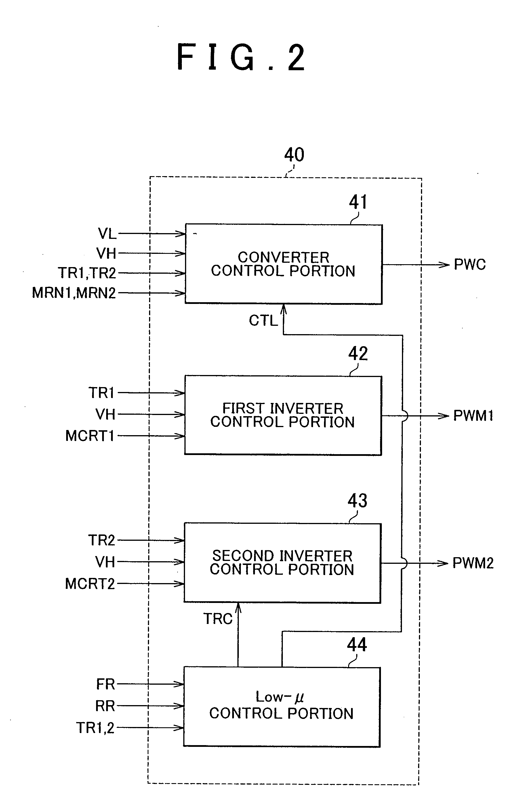
[0112]FIG. 11 is a functional block diagram of the ECU 40B in the third embodiment. As shown in FIG. 1, the configuration of the ECU 40B is the same as the configuration of the ECU 40 in the first embodiment shown in FIG. 2, except that the ECU 40B includes a second inverter control portion 43A instead of the second in...


PUM


Abstract

A control apparatus for an electric vehicle includes a road surface condition detection portion, a slip determination portion, a torque reduction device, and a voltage control device. The electric vehicle includes a motor that generates drive power for the electric vehicle, and a drive device that drives the motor. The road surface condition detection portion detects the condition of a road surface on which the electric vehicle is driven. The slip determination portion determines whether the electric vehicle is slipping. The torque reduction device reduces the torque of the motor when the slip determination portion determines that the electric vehicle is slipping. The voltage control device controls a voltage input to the drive device to reduce the voltage when the road surface condition detection portion determines that the road surface has a friction coefficient lower than a predetermined value.

Description

INCORPORATION BY REFERENCE[0001]The disclosure of Japanese Patent Application No. 2006-038322 filed on Feb. 15, 2006 including the specification, drawings and abstract is incorporated herein by reference in its entirety.BACKGROUND OF THE INVENTION[0002]1. Field of the Invention[0003]The invention relates to a control apparatus and a control method for an electric vehicle. More particularly, the invention relates to a control technology that avoids an overvoltage which is caused by reducing the torque of a motor when a vehicle slips.[0004]2. Description of the Related Art[0005]Japanese Patent Application Publication No. 2005-51850 (JP-A-2005-51850) describes a vehicle in which an overcurrent is prevented from flowing in a motor that outputs power to a drive shaft when the vehicle slips. The vehicle includes a boost converter that boosts a voltage output from a battery; and the motor that receives electric power from the boost converter and outputs the power to the drive shaft of the ...

Claims


Application Information

Patent Timeline
IPC IPC(8): B60K28/16B60L9/18B60K6/445B60W10/08B60W20/00
CPCB60K6/445B60K28/16B60L3/10B60L11/14B60W10/08Y02T10/70B60W2520/26Y02T10/7077Y02T10/7258Y02T10/6239B60W20/00B60L50/16Y02T10/62Y02T10/7072Y02T10/72B60W20/12
Inventor MUTA, KOICHIRONAGAO, IPPEI
Owner TOYOTA JIDOSHA KK
Why Eureka
Try Eureka