Aerodynamic drag reduction systems

Inactive Publication Date: 2007-08-16
SHAHBAZI KHOSROW
View PDF12 Cites 26 Cited by
  • Summary
  • Abstract
  • Description
  • Claims
  • Application Information

AI Technical Summary

Benefits of technology

[0011] The problems identified above are in large part addressed by methods and apparatuses for reducing the aerodynamic drag and/or improving the fuel efficiency of a vehicle by reducing the pressure drag created by the vehicle. One embodiment provides a fan attached to a vehicle, wherein the f

Problems solved by technology

A significant portion of the operational costs of a modern motor vehicle arises from the consumption of fuel.
Gasoline and other fossil fuels are relatively inexpensive at the present time in the United States as compared to the prices in other countries, but the prices are subject to fluctuations and the potential of future increases in the event of political instability in oil-producing regions, increased taxes by governmental entities, or shortages of oil.
Fuel can be very expensive for commuters, vacationers, cross-country truckers, or anyone driving a fossil fuel-powered vehicle.
Increased fuel prices can also have a significant detrimental impact on the economy, as they can deter travel, increase the cost of transportation or manufacture of goods, etc.
Frictional drag derives from friction between the fluid (air) and the surfaces of the vehicle over which it is flowing.
The drag caused by the air in the boundary layer creates frictional drag.
When the airflow separates on the vehicle, as described above, lower pressures are created behind the vehicle th

Method used


Image

  • Aerodynamic drag reduction systems
  • Aerodynamic drag reduction systems
  • Aerodynamic drag reduction systems

Examples


Example

[0040] The following is a detailed description of example embodiments of the invention depicted in the accompanying drawings. The example embodiments are in such detail as to clearly communicate the invention. However, the amount of detail offered is not intended to limit the anticipated variations of embodiments; but, on the contrary, the intention is to cover all modifications, equivalents, and alternatives falling within the spirit and scope of the present invention as defined by the appended claims. The detailed descriptions below are designed to make such embodiments obvious to a person of ordinary skill in the art.

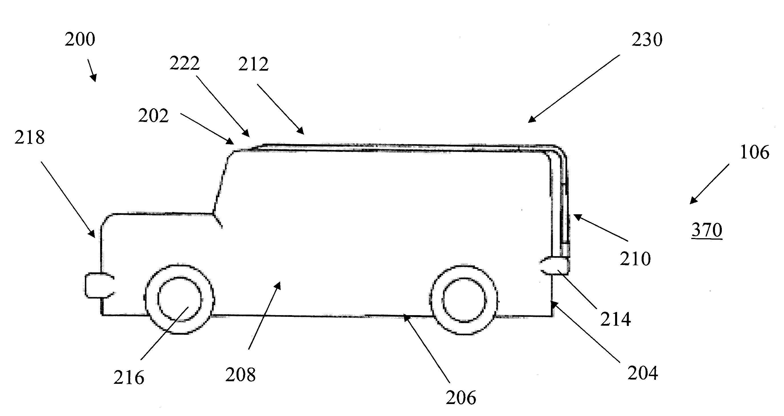
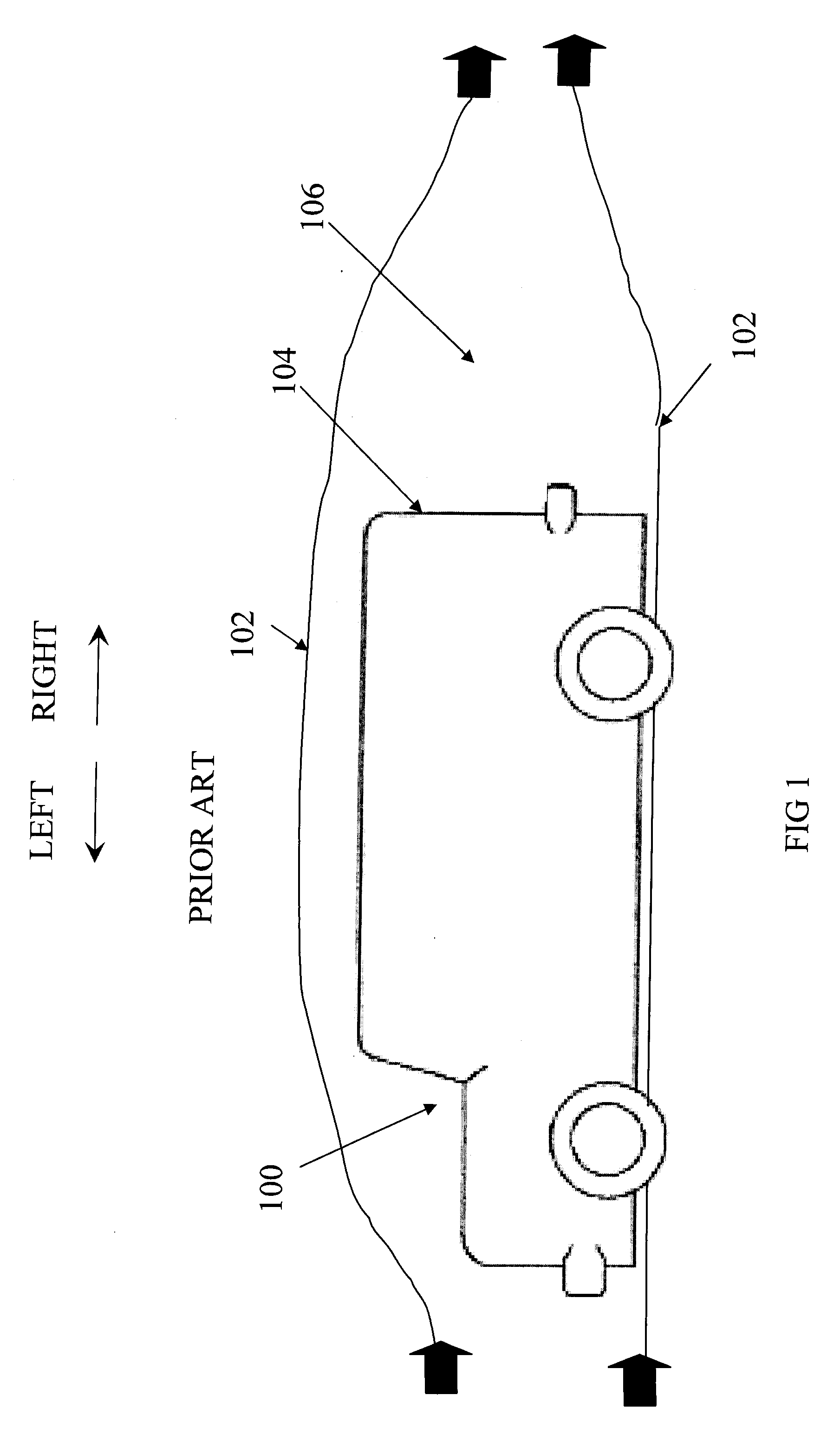
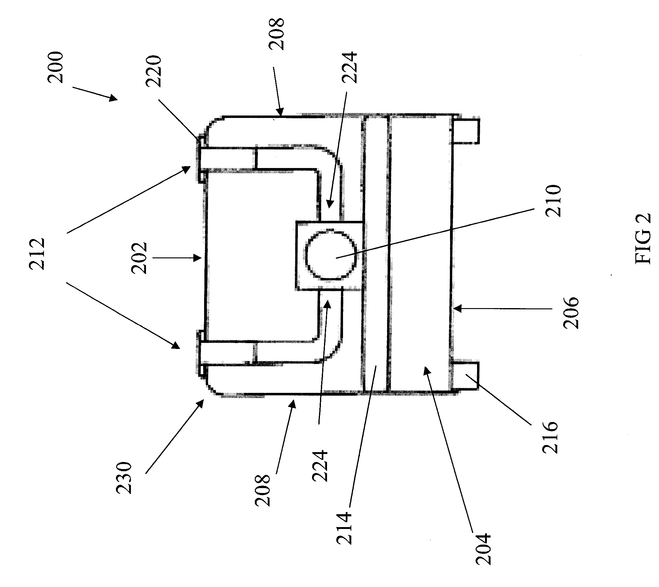
[0041] Generally speaking, methods and apparatuses for reducing the aerodynamic drag of a vehicle are disclosed. More particularly, methods and apparatuses are disclosed for increasing the pressure of air behind the vehicle so as to reduce pressure drag. One embodiment provides one or more fans attached to a vehicle, wherein at least one fan is positioned to direct ...


PUM


Abstract

Systems, methods and media for reducing the aerodynamic drag of vehicles are disclosed. More particularly, embodiments may include at least one fan for directing air into a lower pressure region behind a vehicle in motion in order to reduce pressure drag. Embodiments may also include one or more internal air ducts for directing air from other parts of the vehicle to the at least one fan. In one embodiment, the operation of the at least one fan may be controlled based on sensed conditions, user control, or other means.

Description

CROSS-REFERENCE TO RELATED APPLICATION [0001] Pursuant to 35 USC § 120, this continuation-in-part application claims priority to and benefit of U.S. Utility patent application Ser. No. 11 / 277,903, filed Mar. 29, 2006, on behalf of inventor Khosrow Shahbazi, entitled “CONTROL SYSTEM FOR PRESSURE DRAG REDUCTION SYSTEM”, which is a divisional application claiming priority to U.S. Utility patent application Ser. No. 10 / 883,389, filed Jul. 1, 2004, on behalf of inventor Khosrow Shahbazi, entitled “SYSTEMS, METHODS, AND MEDIA FOR REDUCING THE AERODYNAMIC DRAG OF VEHICLES”, issued as U.S. Pat. No. 7,152,908 on Dec. 26, 2006.FIELD OF INVENTION [0002] The present invention is in the field of vehicles and, in particular, systems for reducing the aerodynamic drag and / or improving the fuel efficiency of a vehicle. More particularly, the present invention relates to systems for reducing the aerodynamic drag of a vehicle in motion by reducing the pressure drag associated with the vehicle via one ...

Claims


Application Information

Patent Timeline
IPC IPC(8): B62D35/00B60R99/00
CPCB62D37/02B62D35/00
Inventor SHAHBAZI, KHOSROW
Owner SHAHBAZI KHOSROW
Why Eureka
Try Eureka