Control system

a control system and control system technology, applied in the direction of program control, dynamo-electric converter control, instruments, etc., can solve the problem of inability to produce stable synchronous control, and achieve the effect of high precision

Inactive Publication Date: 2007-08-16
FANUC LTD
View PDF12 Cites 12 Cited by
  • Summary
  • Abstract
  • Description
  • Claims
  • Application Information

AI Technical Summary

Benefits of technology

[0016]The present invention provides a control system in which the phase difference and cycle difference between timing signals generated by controllers are corrected. In this control system, the phase and cycle between the timing signal of the master unit and the timing signals of the slave units agree with each other and, accordingly, the motors controlled by the master unit and the slave units can be synchronously controlled with high precision.

Problems solved by technology

When the timing signal cycle differs, the actuated timing of the motors driven by the controllers deviates and a stable synchronous control cannot be produced.

Method used


Image

  • Control system
  • Control system
  • Control system

Examples


Embodiment Construction

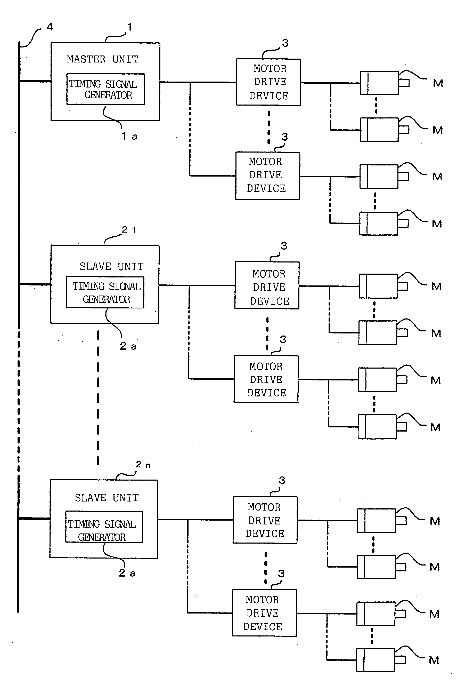
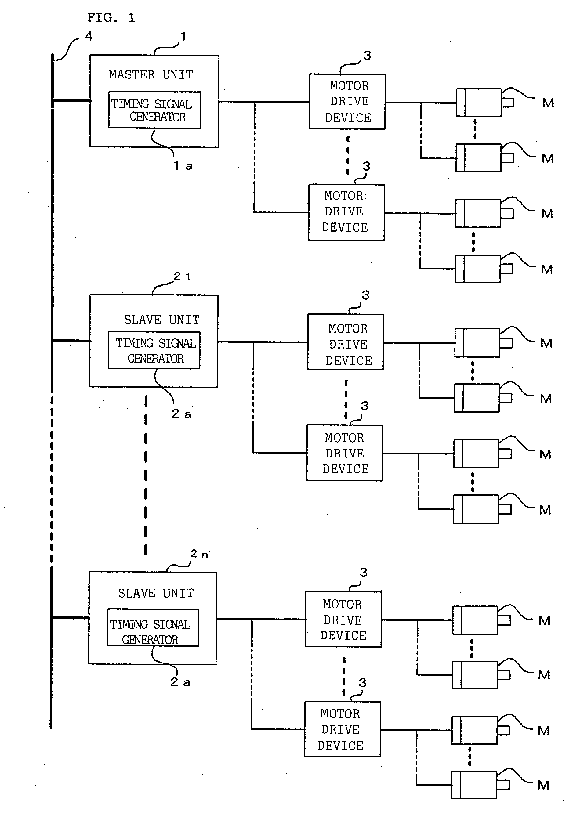
[0021]FIG. 1 is a schematic diagram of one embodiment of a control system according to the present invention. A plurality of controllers including a robot controller and a controller for controlling a machine tool are connected to one another through a communication path 4 such as a serial bus or Ethernet®. In carrying out synchronous control, one of these controllers acts as a master unit 1, while remaining controllers act as slave units 21, 22, . . . , 2n.

[0022]A plurality of motor drive devices 3 are connected to the master unit 1 and, furthermore, a plurality of motors M is connected to each of the motor drive devices 3. Thereupon, the master unit 1 drives and controls the motors M to which it is connected by way of the motor drive devices 3.

[0023]A plurality of motor drive devices 3 are also similarly connected to the slave units 21, 22, . . . , 2n, and a plurality of motors M are connected to each of these motor drive devices 3. Thereupon, the slave units 21, 22 . . . , 2n dr...


PUM


Abstract

A master unit and a plurality of slave units are connected by way of a communication path. The master unit sends to the slave units timing signals generated by its own cycle signal generator by way of a communication path. The slave units determine the cycle difference and the phase difference between a timing signal generated by its own cycle signal generator and the timing signal sent from the master unit and, in accordance therewith, determine a cycle adjustment amount. The cycle signal generators of the slave units adjust the timing signal cycle based on the cycle adjustment amount.

Description

BACKGROUND OF THE INVENTION[0001]1. Field of the Invention[0002]The present invention relates to a synchronizing control system for a plurality of controllers.[0003]2. Description of the Related Art[0004]In a controller such as a numerical controller or a robot controller, the motor control is implemented in accordance with timing signals of a fixed cycle generated by the hardware of the controller, that is to say, by an interpolation cycle (ITP signal). A main CPU of the controller delivers the motion amount of each ITP signal interval to a DSP (digital signal processor) that controls a servomotor. The DSP distributes the command motion amount to each control cycle (position, speed control cycles) obtained by further subdividing of the ITP signal interval to control the position and speed of the motor.[0005]On the other hand, a system in which a controller such as a numerical controller or robot controller is connected in plurality and a plurality of controllers are synchronously o...

Claims


Application Information

Patent Timeline
Patent Type & Authority Applications(United States)
IPC IPC(8): H02P5/46
CPCE05Y2400/30G05B19/0421H03L7/113G05B2219/33273H03L7/0991G05B2219/33094
Inventor AOYAMA, KAZUNARINAKAMURA, MINORUKOMATSU, TAKAAKI
Owner FANUC LTD
Why Eureka
Try Eureka