Multi-carrier communication system

a communication system and carrier technology, applied in the field of multi-carrier communication systems, can solve the problems of significantly reducing the spectral efficiency of the system, non-linearity reducing the efficiency of the amplifier, and the requirement of guard band frequency, so as to increase the complexity of the receiver and the burden of signal processing

Active Publication Date: 2007-08-16
FUJITSU LTD
View PDF5 Cites 39 Cited by
  • Summary
  • Abstract
  • Description
  • Claims
  • Application Information

AI Technical Summary

Benefits of technology

[0018] Embodiments of the present invention seek to alleviate the problems associated with the known techniques, and to provide a technique for enabling a receiver to have knowledge about a phase vector applied to a time domain symbol without unduly increasing the complexity of a receiver and the signal processing burden required to “decode” the received signal.

Problems solved by technology

A disadvantage of FDM systems is that a guard band frequency is required between each modulated sub-carrier to ensure that the spectrum of one sub-carrier does not interfere with the spectrum of another.
The necessity for guard bands in an FDM system significantly lowers the spectral efficiency of the system.
The high PAPR inherent in OFDM systems causes problems when the signal has to be subject to power amplifiers.
This non-linearity reduces the efficiency of the amplifier.
However, these previously proposed techniques have been found to introduce various other problems which negate the improvement seen in the PAPR such as an increase in the required transmit signal power, a reduction in the data rate of the system and an increase in bit error and complexity of the system.
However, this approach utilises bandwidth and increases signalling overhead.
However, the improvements seen in the throughput of the system are countered by a significant increase in receiver complexity.
Another disadvantage of the known blind receiver is that for each OFDM symbol, the same modulation scheme should be used on each sub-carrier so that a mixed modulation scheme employing, for example, QPSK on some sub-carriers and 16QAM on other sub carriers, is not permitted.
Furthermore, the receiver requires an accurate estimation of the channel where a high level modulation scheme is employed (16 / 64 QAM) which may mean that more pilot overhead is required.

Method used


Image

  • Multi-carrier communication system
  • Multi-carrier communication system
  • Multi-carrier communication system

Examples


first embodiment

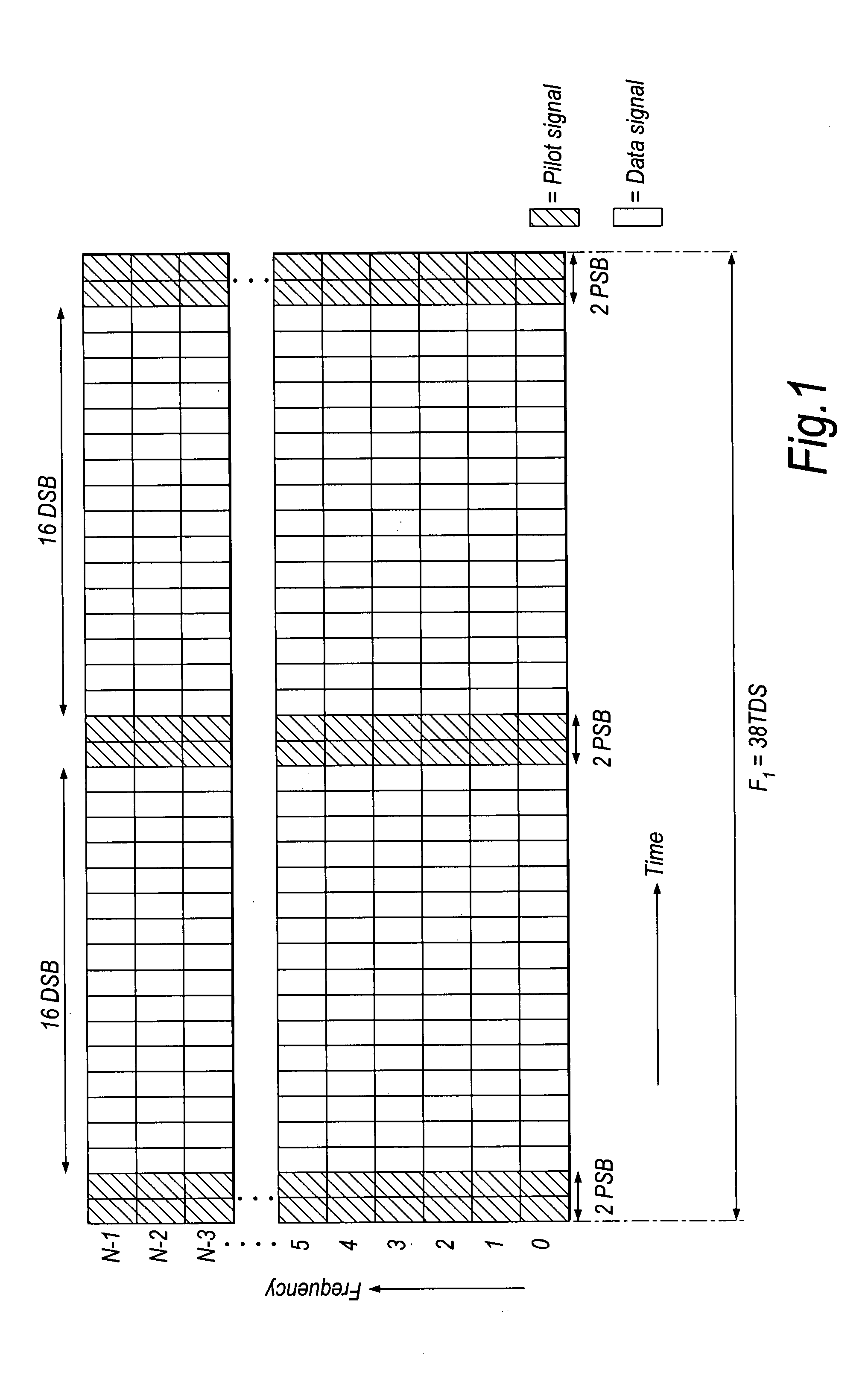
[0056]FIG. 5 shows an example structure of an information unit of a multi-carrier signal comprising N sub-carriers according to the present invention. In this embodiment the pilot signals assigned to carry the phase information are all carried by signals comprised in the second time domain symbol (TDS2) of the information unit. The complete information unit is identical in structure to the information unit shown in FIG. 1 and FIG. 5 illustrates the way in which information about a phase vector Qu applied to a time domain symbol of the information unit may be provided to, or encoded in, the assigned pilot signals. Only the first two pilot signal blocks, PSB1 and PSB2, the first two data symbol blocks DSB1 and DSB2 and the last two data symbol blocks DSBNdata−1 and DSBNdata, comprised in the information unit F1 are illustrated in FIG. 5, where Ndata=32.

[0057] A phase vector, Qu, is applied to each of the data symbol blocks comprised in the information unit shown in FIG. 5. Preferably,...

second embodiment

[0063] Part of an information unit F2 according to the present invention is shown in FIG. 7. In this embodiment, the pilot signals assigned to a particular time domain symbol are carried by sub-carriers in the same time interval as the respective time domain symbol. Thus, TDS2, for example, is provided with a set of pilot signals P1. The pilot signals therefore appear to be arranged “within” the time domain symbol for which the pilot signals carry phase vector information. Thus, in a given time domain symbol (e.g. DSB1), a number of the sub-carriers, Npilot, are each modulated with the pilot signal whilst the remaining sub-carriers, N-Npilot, are modulated with data symbols. It can be seen from FIG. 7 that the pilot signals are scattered within the frequency domain of the time domain symbol. However, the positions of the Npilot sub-carriers within the frequency domain should be known, or determinable by, the receiver. It should be appreciated that the pattern, or arrangement, of the...


PUM


Abstract

The present application relates to a communication method in which a succession of time domain symbols (TDS) are transmitted by a transmitter to one or more receivers. Each time domain symbol has a plurality of signals which are transmitted in parallel by the transmitter. The signals may comprise data signals or pilot signals. At the transmitter, a set of pilot signals assigned to a given time domain symbol is provided with information about a phase vector applied to the time domain symbol. The phase vector is preferably selected with consideration of the reduction in the ratio of peak-to-average-power which can be achieved when the vector is applied to the time domain symbol. Transmitters and receivers for use in the communication method are also provided. The invention is particularly application to OFDM communication systems.

Description

BACKGROUND OF THE INVENTION [0001] 1. Field of the Invention [0002] The present invention relates to multi-carrier communication systems, such as frequency division multiplexing (FDM) systems and orthogonal division multiplexing (OFDM) systems, transmitters, receivers and to methods of transmitting a signal in such systems. [0003] 2. Description of the Related Art [0004] In a multi-carrier transmission system, such as FDM or OFDM, a single data stream is modulated onto N parallel sub-carriers, each sub-carrier signal having its own frequency range. This allows the total bandwidth (i.e. the amount of data to be sent in a given time interval) to be divided over a plurality of sub-carriers thereby increasing the duration of each data symbol. Since each sub-carrier has a lower information rate, multi-carrier systems benefit from enhanced immunity to impulse noise and reflections. A disadvantage of FDM systems is that a guard band frequency is required between each modulated sub-carrier ...

Claims


Application Information

Patent Timeline
Patent Type & Authority Applications(United States)
IPC IPC(8): H04B3/10H04J3/14
CPCH04L27/2621H04B7/2621
Inventor AWAD, YASSIN ADEN
Owner FUJITSU LTD
Why Eureka
Try Eureka