Multichamber tank for motor vehicles

Active Publication Date: 2007-08-16
TESMA MOTOREN UND GETRIEBETECHN
View PDF5 Cites 17 Cited by
  • Summary
  • Abstract
  • Description
  • Claims
  • Application Information

AI Technical Summary

Benefits of technology

[0006] The use of the pump for only one purpose makes it possible to select a turbopump with a large mass flow and a small delivery head, for example a correspondingly designed centrifugal pump, a semi-axial-flow pump or even an axial-flow pump or screw pump. Accordingly, the connecting line also has a large cross section, so that

Problems solved by technology

This shape requires special precautions for drawing in and delivering the fuel to the engine because a single feed pump unit in a single chamber is clearly inadequate.
If the vertex is very h

Method used


Image

  • Multichamber tank for motor vehicles
  • Multichamber tank for motor vehicles
  • Multichamber tank for motor vehicles

Examples


Embodiment Construction

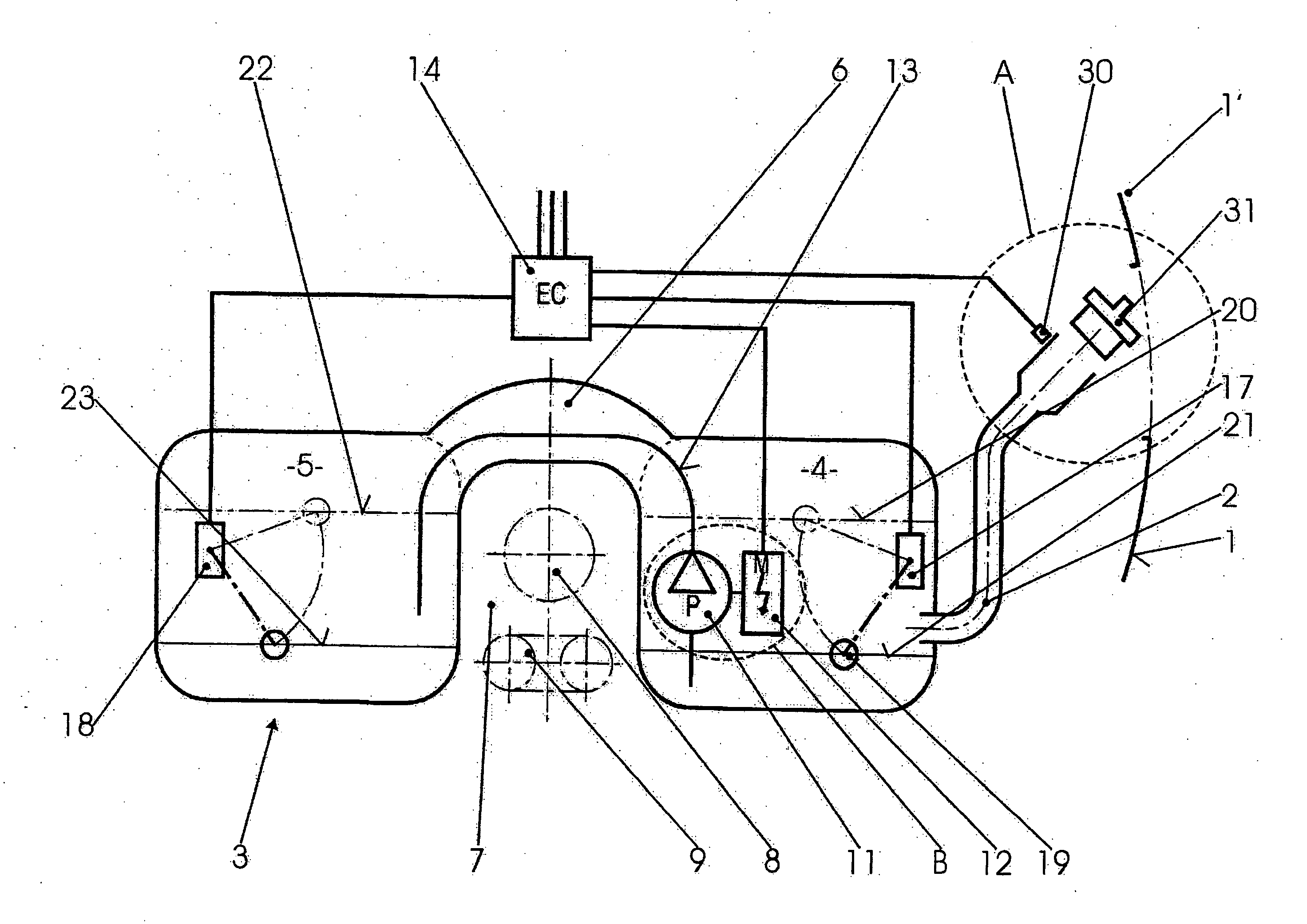
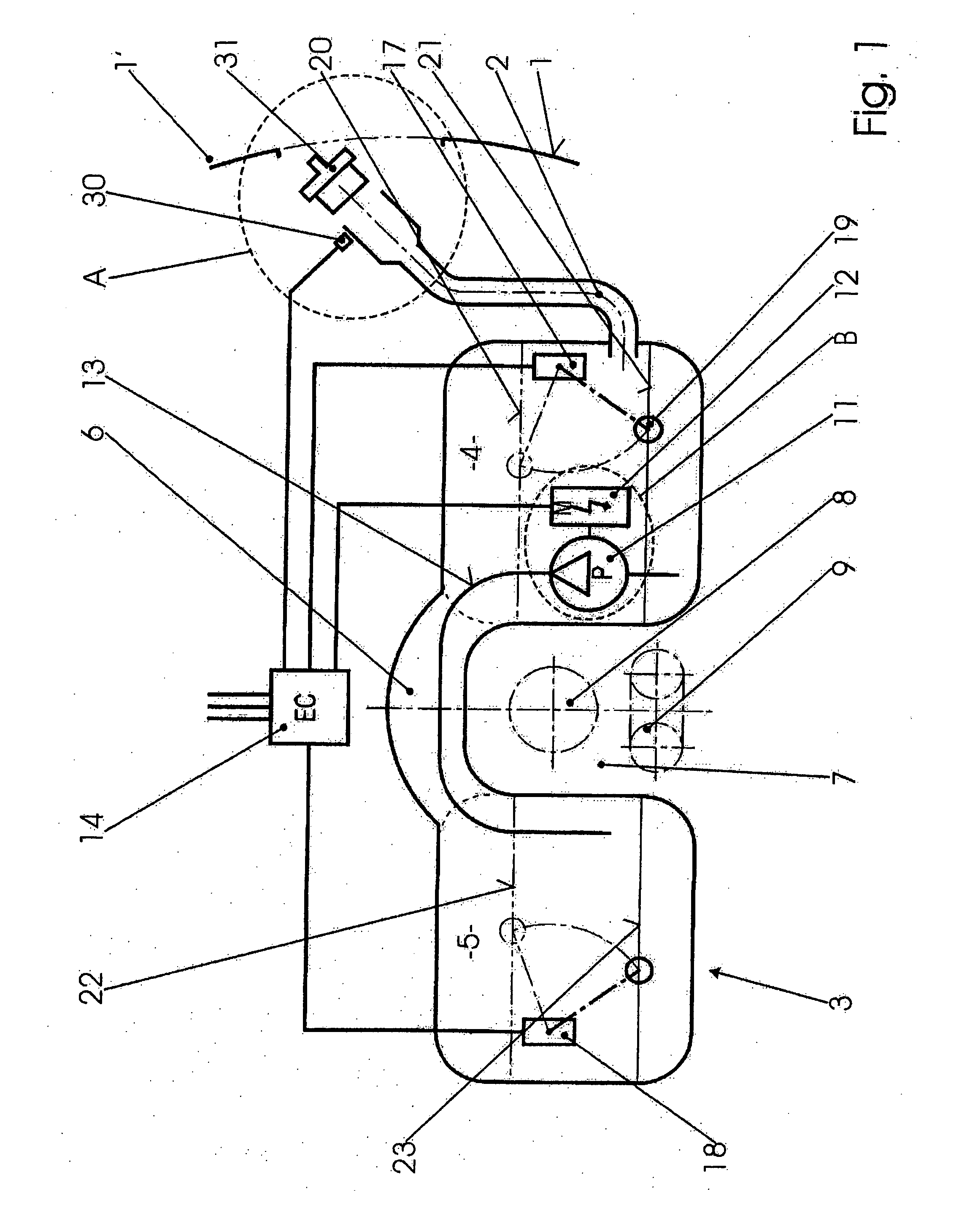
[0015] In FIG. 1, the side wall 1 of a motor vehicle is only indicated. A filler pipe 2 for filling-up, which leads into a tank designated as a whole by 3, is accessible through an opening 1′ in the side wall 1. The tank consists of two chambers 4, 5, one on the right side of the motor vehicle and one on the left, and a raised and constricted region 6 between them. A free space 7, which provides space for a propeller shaft 8 and if appropriate an exhaust 9 as well, is thus created below the region 6 and between the two chambers 4, 5.

[0016] A special pump 11 with an electric drive motor 12 is located as low down as possible inside the right chamber 4. This pump 11 serves only for level equalization during filling-up. For normal operation, a separate installation of pumps and if appropriate sucking jet pumps is provided, which conveys the fuel to the internal combustion engine of the vehicle. This does not constitute subject matter of the invention and can be of any type of construct...


PUM

PropertyMeasurementUnit
Timeaaaaaaaaaa
Contentaaaaaaaaaa
Mass flow rateaaaaaaaaaa

Abstract

A multichamber tank for motor vehicles comprises two chambers (4, 5) connected via a constricted region (6) located high up in the chambers, a first chamber (4) having a filler neck (2), and a line (13) bridging the constriction forming the connection to a second chamber (5). In order that both chambers are filled at approximately the same speed during filling-up through the filler neck (2), a pump (11) designed for level equalization during filling-up and driven by an electric motor (12) is provided in the line (13), and a level sensor (17, 18) is provided in each of the two chambers (4, 5), the output signals of which sensors are available to a control unit (14) which controls the electric motor (12) of the pump (11).

Description

BACKGROUND OF THE INVENTION [0001] The invention relates to a multichamber tank for motor vehicles, the chambers of which meet via a constricted region located high up, a first chamber having a filler neck, and a line bridging the constriction forming the connection to a second chamber. Such fuel tanks are found in motor vehicles with rear-wheel drive, for safety reasons in front of the rear axle, and are shaped in such a way that sufficient space remains free for passage of the propeller shaft leading to the rear axle. This accounts for their shape, because of which they are also designated as saddle tanks. [0002] This shape requires special precautions for drawing in and delivering the fuel to the engine because a single feed pump unit in a single chamber is clearly inadequate. For this purpose, either a number of feed pump units are necessary, one in each chamber, or only one in one chamber and a sucking jet pump in the second chamber. An example of the first arrangement is known...

Claims


Application Information

Patent Timeline
IPC IPC(8): F04B49/00
CPCB60K15/077B60K2015/03138F02M37/10F02D33/006F02M37/0094B60K2015/03223
Inventor PALVOLGYI, SANDOR
Owner TESMA MOTOREN UND GETRIEBETECHN
Why Eureka
Try Eureka