Valve system of V-type engine

Active Publication Date: 2007-08-23
TOYOTA JIDOSHA KK
View PDF6 Cites 14 Cited by
  • Summary
  • Abstract
  • Description
  • Claims
  • Application Information

AI Technical Summary

Benefits of technology

[0020]In the valve system as described just above, when the phase of the valve cams relative to the crankshaft is changed by the variable valve timing mechanism, the phase of the pump cam relative to the camshaft is changed in synchronism with the change in the phase of the valve cams. Therefore, the relationship in phase or angular posit

Problems solved by technology

Meanwhile, the camshaft on which the pump cam as well as the valve cams are formed is subjected to torque fluctuations in driving the fuel pump, in addition to torque fluctuations in driving the engine valves.
If the driving torque fluctuations associated with the fuel pump are superimposed on those associated with the engine valves to increase the amplitude of total torque fluctuations, excessive tension is applied to a drive member, such as a timing belt or a timing chain, for driving

Method used


Image

  • Valve system of V-type engine
  • Valve system of V-type engine
  • Valve system of V-type engine

Examples


first embodiment

[0031]Referring to FIG. 1 through FIG. 6, a valve system of a V-type engine constructed according to the invention will be described in detail.

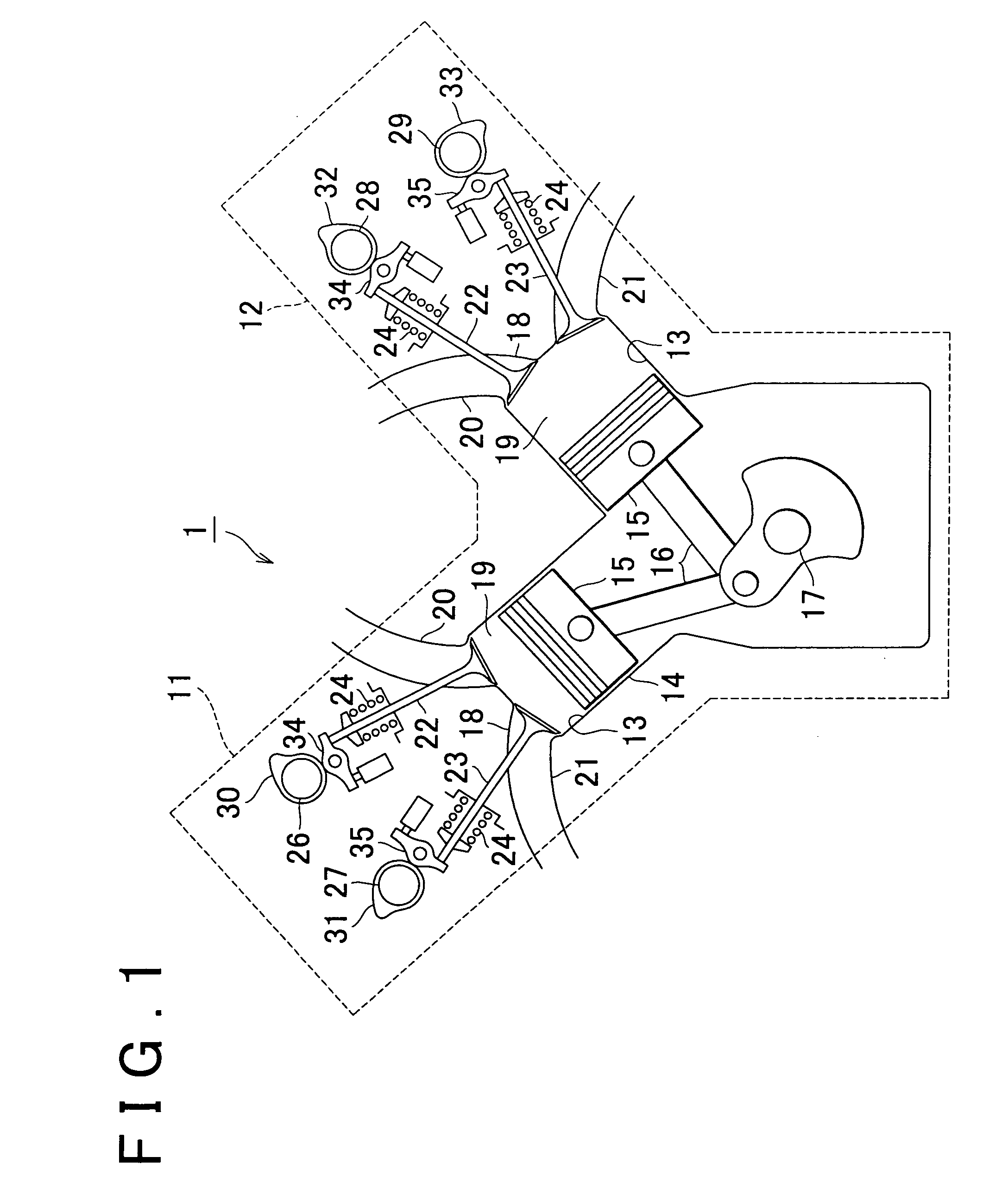
[0032]FIG. 1 schematically shows a V-type engine 1 in which the valve system of according to the first embodiment is installed. The V-type engine 1 has a left bank 11 and a right bank 12 which are arranged in the shape of the letter V with an angular spacing of 90° between the banks. The V-type engine 1 is an eight-cylinder engine in which each of the left and right banks 11, 12 has four cylinders. The V-type engine 1 includes a cylinder block 14 that defines the respective cylinders 13, and a piston 15 is received in each of the cylinders 13 such that the piston 15 reciprocates in the corresponding cylinder 13. The piston 15 is connected via a connecting rod 16 to a crankshaft 17 provided in the lower part of the V-type engine 1. The reciprocating motion of the piston 15 is converted into the rotary motion of the crankshaft 17 by use of the ...

second embodiment

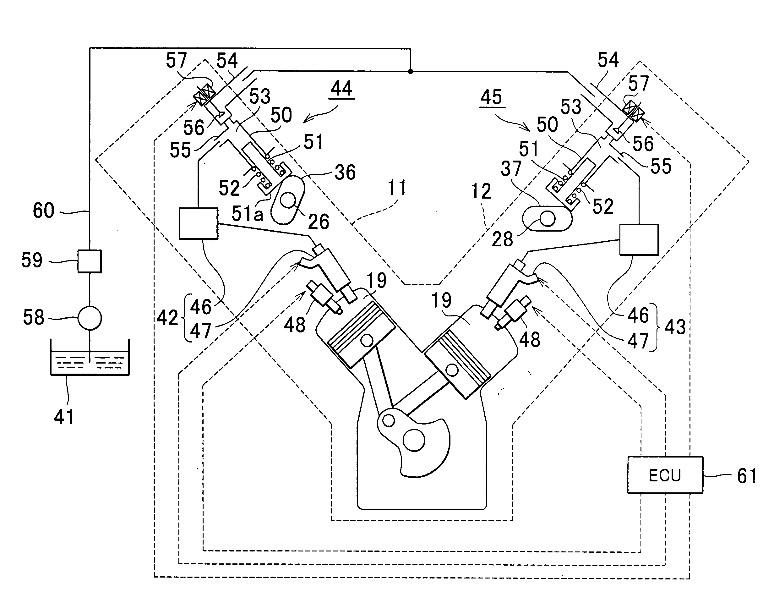
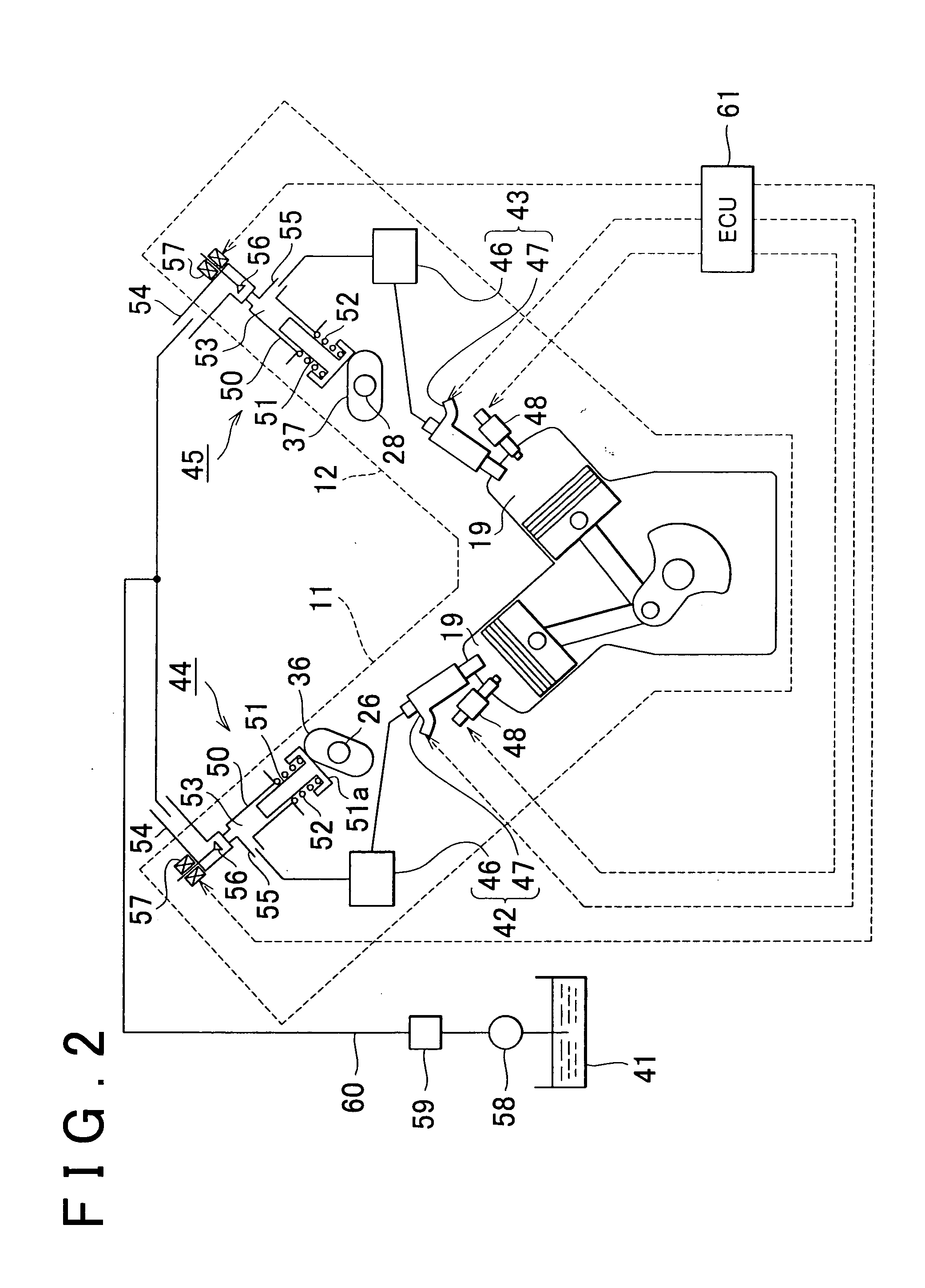
[0069]In the valve system of the V-type engine 1 a pump cam 71 formed on the first intake camshaft 26 and a pump cam 72 formed on the second intake camshaft 28 rotate in opposite phase to each other (i.e., with a phase difference of 180°CA) to drive the fuel pumps 44, 45 in opposite phase to each other, in order to suppress pulsation of the fuel. As explained below, the phase of the pump cam 71, 72 is set to suppress or reduce fluctuations in torque applied to each of the intake camshafts 26, 28. FIG. 7A and FIG. 7B show the configurations of the pump cams 71, 72 on the intake camshafts 26, 28, respectively. In FIGS. 7A and 7B, the intake camshafts 26, 28 rotate in the direction of arrow R. Each of the pump cams 71, 72 has the shape of an ellipse, and two cam noses having the same shape are formed at equal intervals over the entire circumference of the pump cam 71, 72. FIG. 7A illustrates a condition in which the top E of one of the cam noses of the pump cam 71 acts on the plunger ...


PUM


Abstract

A valve system of a V-type engine in which a camshaft provided in each bank is formed with valve cams that open and close engine valves and a pump cam for driving a fuel pump, the phase of the pump cam relative to the valve cams is set such that the crank angle at which driving torque of the pump cam is maximized does not coincide with the crank angle at which driving torque of each of the valve cams is maximized.

Description

INCORPORATION BY REFERENCE[0001]The disclosure of Japanese Patent Application No. 2006-043787 filed on Feb. 21, 2006, including the specification, drawings and abstract, is incorporated herein by reference in its entirety.BACKGROUND OF THE INVENTION[0002]1. Field of the Invention[0003]The invention relates to a valve system of a V-type engine in which a camshaft provided in each bank of the engine is formed with valve cams for driving (i.e., opening and closing) engine valves and a pump cam for driving a fuel pump that feeds fuel under pressure to a fuel injection device.[0004]2. Description of Related Art[0005]There is known a valve system in which a fuel pump that delivers fuel under pressure to a fuel injection device is driven by a camshaft on which valve cams for driving (i.e., opening and closing) engine valves, such as the intake valves or the exhaust valves, are formed. In the known valve system, a piston of the fuel pump is urged by a spring, or the like, into contact with ...

Claims


Application Information

Patent Timeline
IPC IPC(8): F01L1/34F01L1/02
CPCF01L1/024F01L1/08F01L1/16F01L1/34F02M59/102F01L2800/00F01L2800/08F01L2810/03F01L2820/01F01L2001/0537
Inventor IMAMURA, TOSHIO
Owner TOYOTA JIDOSHA KK
Why Eureka
Try Eureka