Eccentric rotor and flat motor comprising same

a technology of eccentric rotor and flat motor, which is applied in the direction of dynamo-electric machines, electrical apparatus, dc commutators, etc., can solve the problems of design restrictions, the cylindrical motor cannot be placed in a device, and the inability to miniaturize a portable device, etc., to achieve convenient configuration, stable rotational torque, and sufficient weight

Inactive Publication Date: 2007-08-23
TOKYO PARTS IND CO LTD
View PDF0 Cites 9 Cited by
  • Summary
  • Abstract
  • Description
  • Claims
  • Application Information

AI Technical Summary

Benefits of technology

[0024]According to the first aspect of the invention, because the reference electric opening angle for the effective conductor of each air-core coil can be set as wide as the magnetic pole opening angle, the magnetic field of the magnet with which the coils will be combined can be effectively used, improving motor efficiency.
[0035]According to the eleventh aspect of the invention, sufficient vibrations can be secured even with a small size, achieving a flat vibration motor having sufficient impact resistance.

Problems solved by technology

However, with the above conventional silent call mechanism in which the eccentric weight W is added to the output shaft S, a space for rotation of the eccentric weight W needs to be considered, entailing the problem of design restrictions.
Further, such cylindrical motor cannot be placed in a device as is, and usually requires a member for attachment.
For this reason, in some devices to which a motor is to be mounted, the eccentric weight rotation space and the member for attaching a motor take up much space, inhibiting miniaturization of a portable device.
Further, the efficiency of a cylindrical motor is only 20% to 30%, raising the problem that when an attempt is made to achieve a desired vibration amount, the current consumed becomes overly large.
Therefore, it is difficult to solder without damaging the armature coils.
However, because a resistance that makes no contribution to torque is inserted therein, efficiency degrades.
However, if an attempt is made to secure space for further providing three chip-type spark quenching elements, for the purpose of prolonging life, there is hardly any space for such disposition.
With such a configuration, it is even more difficult to secure a space for disposing an eccentric weight for greater vibration, and a space for disposing chip-type spark quenching elements for a longer life.

Method used


Image

  • Eccentric rotor and flat motor comprising same
  • Eccentric rotor and flat motor comprising same
  • Eccentric rotor and flat motor comprising same

Examples


third embodiment

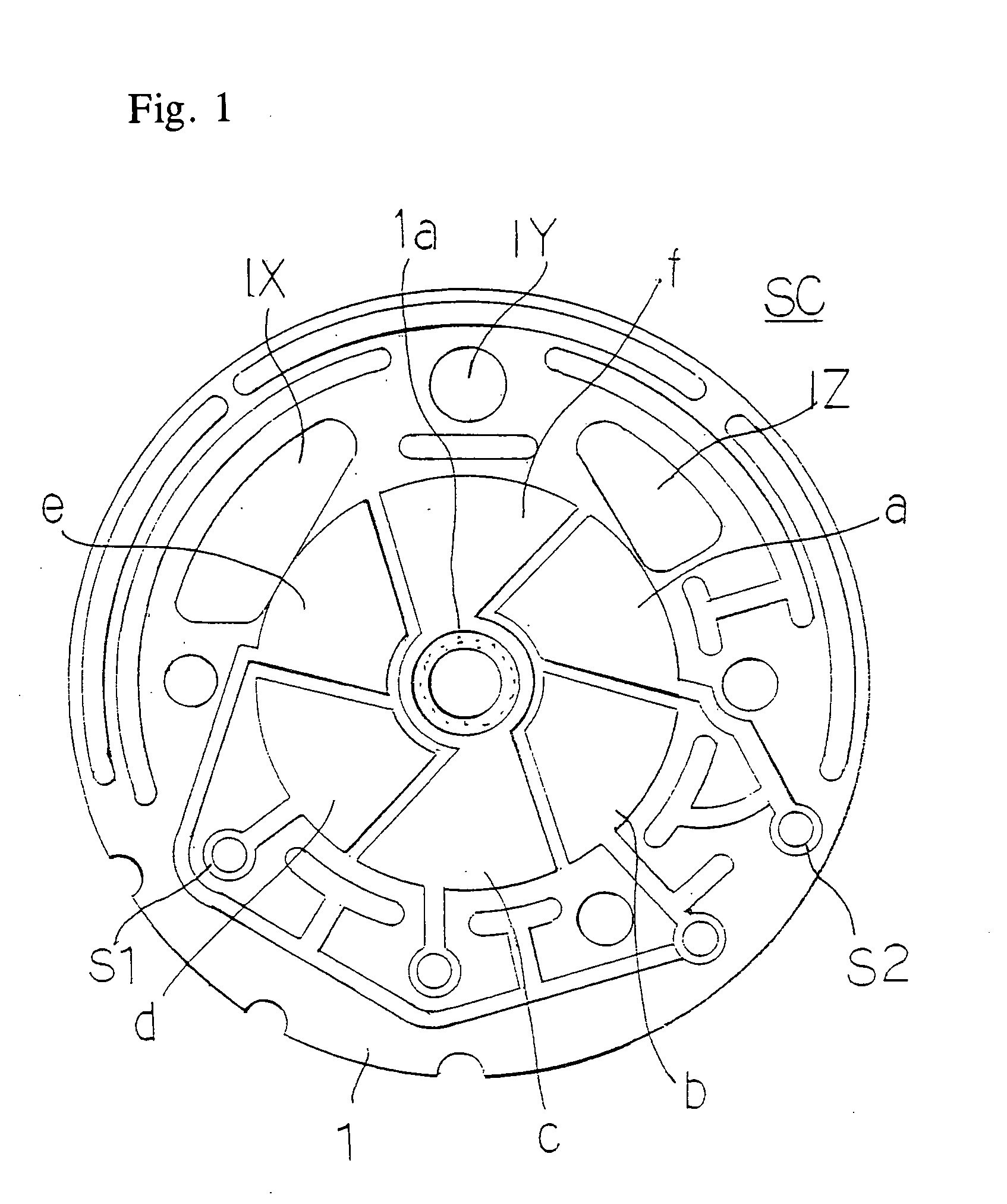
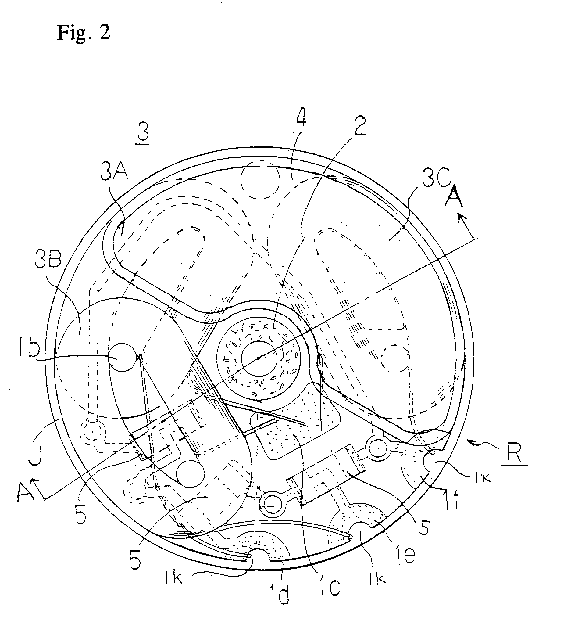
[0069]Next, in accordance with a third embodiment, a variation of the eccentric rotor of FIGS. 1 and 2 will be shown. Even if the shape is slightly different, members performing the same functions are assigned the same legends as above, and the explanation thereof is omitted.

[0070]In FIGS. 5, 6 and 7, 11 is a printed wiring board with a thickness of about 0.1 mm, with copper foil formed on both sides. When seen from a plan view, the printed wiring board 11 has a substantially fan-shaped exterior shape, and comprises a shaft through hole 1 a at the center thereof. Further, the printed wiring board 11 has a commutator formed at the center on one side thereof, and on the center of the other side of the printed wiring board 11, a bearing 2. Radially outward of the bearing 2, the first wound air-core coil 3A is disposed as an armature, using the guide hole 1b etc. for adhesion and fixture to the printed wiring board 11. The wound air-core coil 3A has an effective conductor with an openin...

fourth embodiment

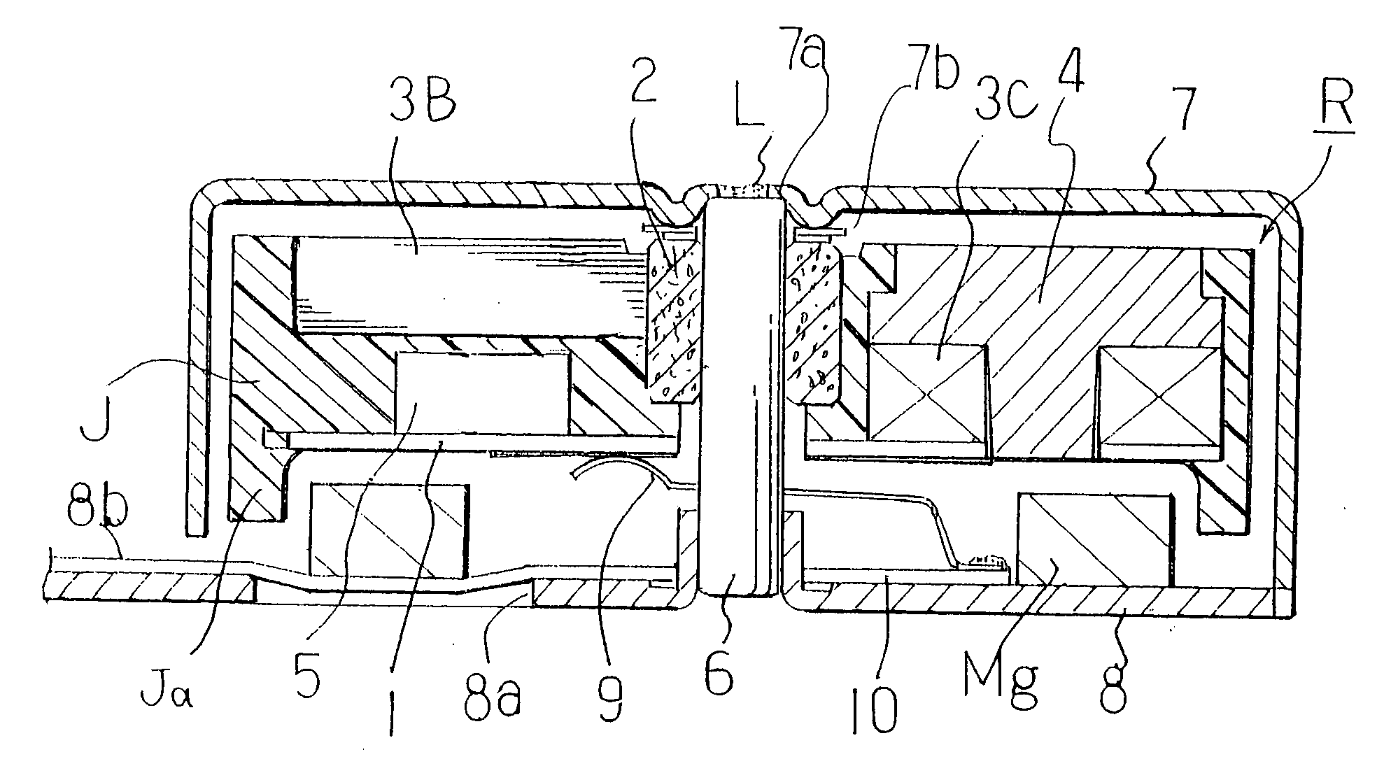
[0082]The device shown in FIG. 7, relating to a fourth embodiment, includes a flat vibration motor comprising such an eccentric rotor R1. While the members are identical to those of FIG. 3, there is a slight difference in the constitution of the eccentric weight 44, an explanation thereof will be given.

[0083]The main component 4a of the eccentric weight 44 is disposed so that a part of the main component 4a is disposed as an arc protrusion 4c, ensuring impact resistance at time of a drop test.

[0084]The diagram shown in FIG. 8 is to explain the operations of the flat vibration motor shown in FIG. 7. The commutator segment land and commutator segment (not shown in the drawings) are assigned the same legend as above when the positions are the same.

[0085]In FIG. 8 as well, precisely when the negative brush 9 bridges the commutator segment c and commutator segment d, and a current to be supplied from the positive brush 9 via the commutator segment b, the current flows through all the coi...

fifth embodiment

[0086]Next, in connection with a fifth embodiment, FIG. 9 shows another variation of the eccentric rotor of FIG. 2. Members identical to those described above are assigned the same legends and the explanation thereof is omitted.

[0087]The eccentric rotor R2 comprises, as an armature 33 on the other side of the printed wiring board 111, only first and second wound air-core coils 3A, 3B displaced by 60° and overlapping each other. More specifically, the eccentric rotor R2 is such that the third wound air-core coil of FIG. 6 is omitted, so that the three coils are reduced in number to two, and the wiring terminals of the first and second coils are connected to each other.

[0088]The second air-core coil 3B is disposed above and displaced 60° from the first wound air-core coil 3A. In the space created between the second wound air-core coil 3B and printed wiring board 111, a spark quenching element 5 such as a chip capacitor is disposed.

[0089]For this reason, because the space for dispositi...


PUM


Abstract

A printed wiring board includes a commutator at a rotation center thereof on one side and a bearing at the rotation center on the other side, first, second and third wound air-core coils having an effective conductor opened to the magnetic pole opening angle, and an eccentric weight comprising a main component and a supplementary part formed so as to be no thicker than the first wound air-core coil and disposed so that the main component does not protrude axially upward of the second and third wound air-core coils. The second wound air-core coil and third wound air-core coil partially overlap both sides of the first wound air-core coil implanted on the printed wiring board, so that the supplementary part of the eccentric weight and a portion of the spark quenching elements are accommodated in the axial space created on outward of both sides of the first wound air-core coil and the main component of the eccentric weight is disposed so as to be on the side opposite the first wound air-core coil across the bearing.

Description

BACKGROUND OF THE INVENTION[0001]The present invention relates to a flat vibration motor used for silent call mechanism of a portable communication device, more specifically, to an improvement of an eccentric rotor serving as a main component thereof.[0002]Conventionally, for example, as shown in FIG. 11, a known silent call mechanism for a pager and portable phone and the like includes a cylindrical DC motor M comprising a tungsten eccentric weight W on an output shaft S. Rotation of a rotor causes the eccentric weight W to rotate, generating vibration. However, with the above conventional silent call mechanism in which the eccentric weight W is added to the output shaft S, a space for rotation of the eccentric weight W needs to be considered, entailing the problem of design restrictions.[0003]Further, recently, cylindrical DC motors with a diameter of 4mm have been used. However, even with a motor with a diameter of 4mm, the space for rotation of an eccentric weight disposed on an...

Claims


Application Information

Patent Timeline
Patent Type & Authority Applications(United States)
IPC IPC(8): H02K7/06H02K7/10
CPCH02K7/063H02K23/54H02K23/04
Inventor YAMAGUCHI, TADAOSOHARA, KATSUHITO
Owner TOKYO PARTS IND CO LTD
Why Eureka
Try Eureka