Method and device for controlling a multiphase electronically commutated motor

a technology of electronic commutation and multi-phase motor, which is applied in the direction of automatic controllers, electric variable regulation, synchronous motor starters, etc., can solve the problem of not being able to understand phraseology in the sense, and achieve the effect of precise and technically simple detection of control-relevant variables

Inactive Publication Date: 2007-08-23
DIEHL AKO STIFTUNG
View PDF11 Cites 36 Cited by
  • Summary
  • Abstract
  • Description
  • Claims
  • Application Information

AI Technical Summary

Benefits of technology

[0007] It is accordingly an object of the invention to provide a method and a device for controlling a multiphase, electronically commutated motor which overcomes the above-mentioned disadvantages of the prior art methods and devices o...

Problems solved by technology

However, this phraseology is not to be understood in ...

Method used


Image

  • Method and device for controlling a multiphase electronically commutated motor
  • Method and device for controlling a multiphase electronically commutated motor
  • Method and device for controlling a multiphase electronically commutated motor

Examples


Embodiment Construction

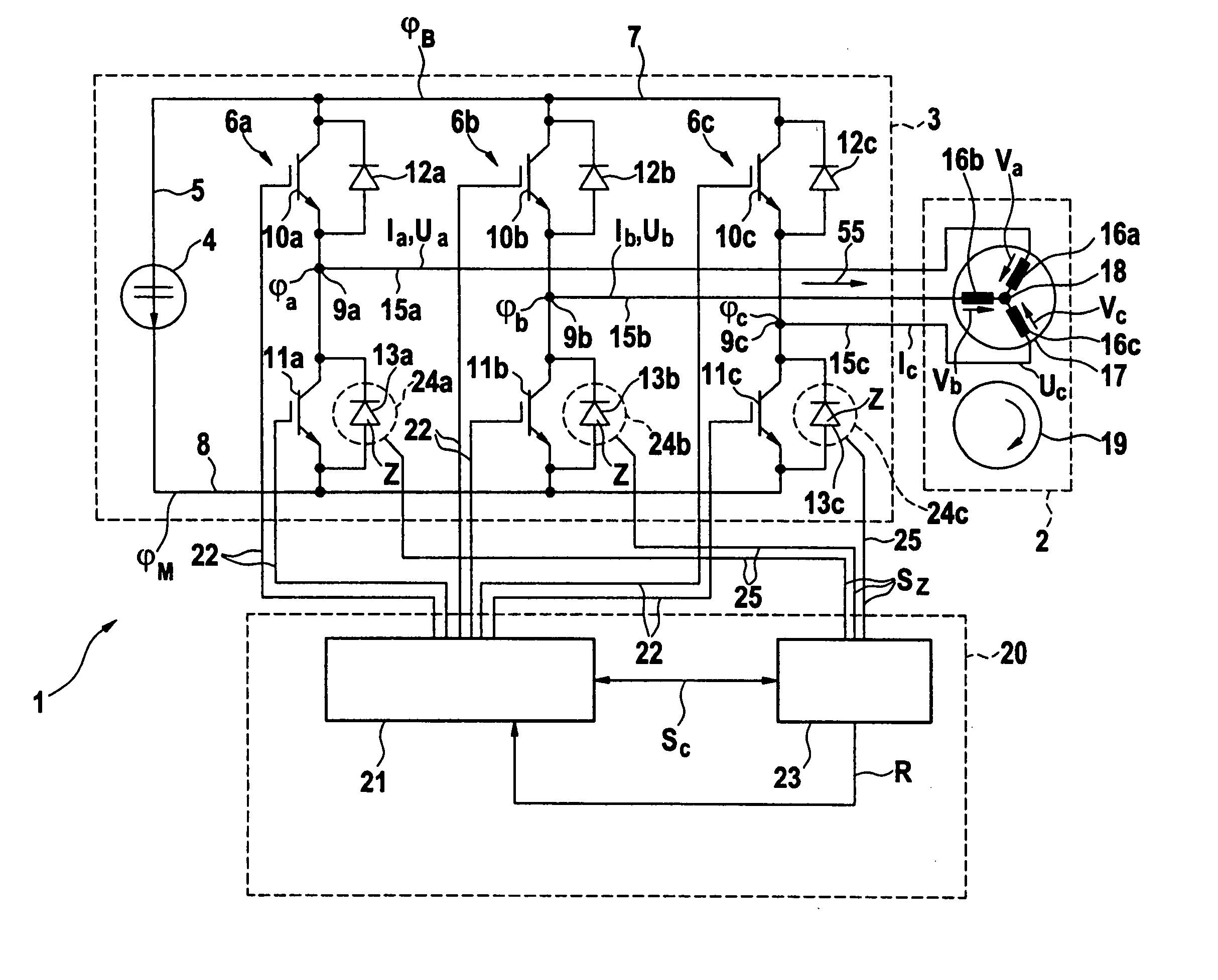
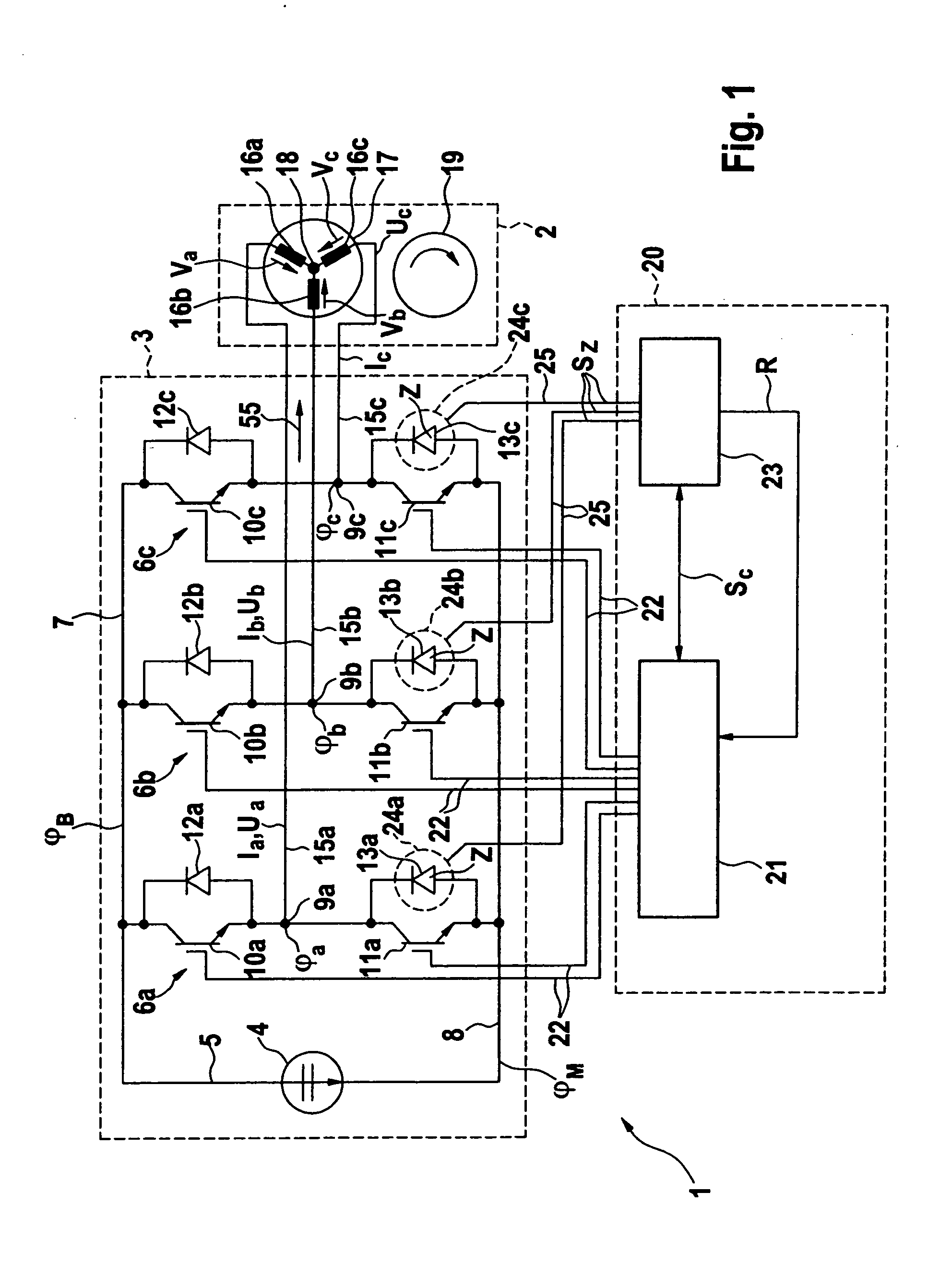
[0040] Components and elements which correspond to one another are denoted by the same designations throughout the figures. Referring now to the figures of the drawing in detail and first, particularly, to FIG. 1 thereof, there is shown a simplified schematic circuit diagram of a device 1 for controlling a three-phase, electronically commutated motor 2. The motor 2 is, for example, a brushless synchronous motor with a permanent magnet. The method described below and the associated device 1 can, however, also be used to control other motor types, in particular in the case of an asynchronous motor or a reluctant synchronous motor.

[0041] The device 1 contains an inverter-side bridge circuit 3 that is supplied with voltage by a DC voltage source 4 via a voltage intermediate circuit 5. The bridge circuit 3 contains three phase half bridges 6a, 6b, 6c that are connected in a parallel circuit in each case between a positive pole 7 and a negative pole 8 of the voltage intermediate circuit ...


PUM


Abstract

A method is specified for controlling a multiphase motor that is commutated by an inverter-side bridge circuit, in the course of which a particularly precise and technically simple detection of a control-relevant variable of a considered motor phase, in particular of a motor phase current and/or a back EMF voltage and/or a variable derived therefrom, takes place. It is provided here to determine the control-relevant variable with the aid of the current state of a freewheeling diode that is disposed in a phase half bridge, assigned to the respective motor phase, of the bridge circuit, the current state being detected during an on time in which a power switch, connected in parallel with the freewheeling diode, of the phase half bridge exhibits a conducting state, and a power switch connected in series with the freewheeling diode exhibits a blocking state.

Description

BACKGROUND OF THE INVENTION Field of the Invention [0001] The invention relates to a method for controlling a multiphase, electronically commutated motor. The invention also relates to a device for carrying out the method. [0002] An inverter that is usually implemented in the form of a bridge circuit is provided in an electronically commutated (electric) motor for the purpose of commutation, that is to say for driving the motor phases. Such a bridge circuit contains a number of phase half bridges that corresponds to the number of the motor phases, each phase half bridge being connected via a voltage intermediate circuit to the positive pole and the negative pole of a DC voltage source, and containing at a center tap a phase terminal for connecting an assigned motor phase. Within each phase half bridge, a power switch on the high-potential side is disposed between the phase terminal and the positive pole, and a power switch on the low-potential side is disposed between the phase term...

Claims


Application Information

Patent Timeline
IPC IPC(8): H02P25/12
CPCH02M2001/0009H02P6/182H03K17/18H03K17/08142H02P27/06H02M1/0009
Inventor WEINMANN, MARTINMULLER, ALEXANDERZEH, STEFAN
Owner DIEHL AKO STIFTUNG
Why Eureka
Try Eureka