
Apparatus and method for providing fluid for immersion lithography

Inactive Publication Date: 2007-08-23
NIKON CORP
View PDF3 Cites 36 Cited by
  • Summary
  • Abstract
  • Description
  • Claims
  • Application Information

AI Technical Summary

Benefits of technology

[0006] Embodiments of the invention are directed to systems and methods of controlling the fluid flow and pressure to provide stable conditions for immersion lithography. A fluid is provided in a space between the lens and the substrate during the immersion lithography process. Fluid is supplied to the space and is recovered from the space through a porous member in fluidic communication with the space. Maintaining the pressure in the porous member under the bubble point of the porous member can eliminate noise created by mixing air with the fluid during fluid recovery. The bubble point is a characteristic of the porous member that depends on the size of the holes in the porous member (the largest hole) and the contact angle that the fluid forms with the porous member (as a parameter based on the property of the porous material and the property of the fluid). Because the bubble point is typically a very low pressure, the control of this low pressure becomes an important issue.

Problems solved by technology

Because the bubble point is typically a very low pressure, the control of this low pressure becomes an important issue.

Method used


Image

  • Apparatus and method for providing fluid for immersion lithography
  • Apparatus and method for providing fluid for immersion lithography
  • Apparatus and method for providing fluid for immersion lithography

Examples


Embodiment Construction

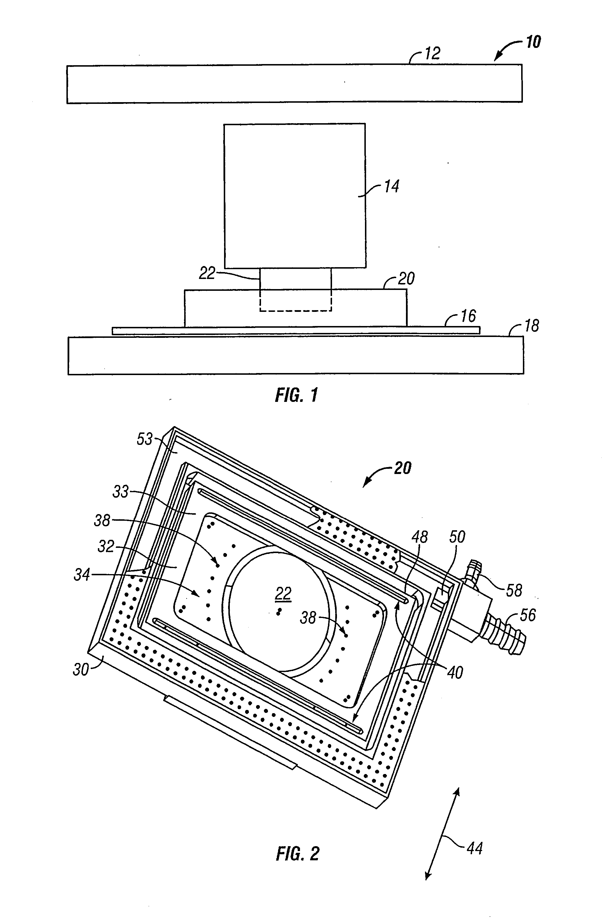
[0023]FIG. 1 shows an immersion lithography system 10 including a reticle stage 12 on which a reticle is supported, a projection lens 14, and a wafer 16 supported on a wafer stage 18. An immersion apparatus 20, which is sometimes referred to herein as a showerhead or a nozzle, is disposed around the final optical element 22 of the projection lens 14 to provide and recover a fluid, which may be a liquid such as water or a gas, between the final optical element 22 and the wafer 16. In the present embodiment, the immersion lithography system 10 is a scanning lithography system in which the reticle and the wafer 16 are moved synchronously in respective scanning directions during a scanning exposure.

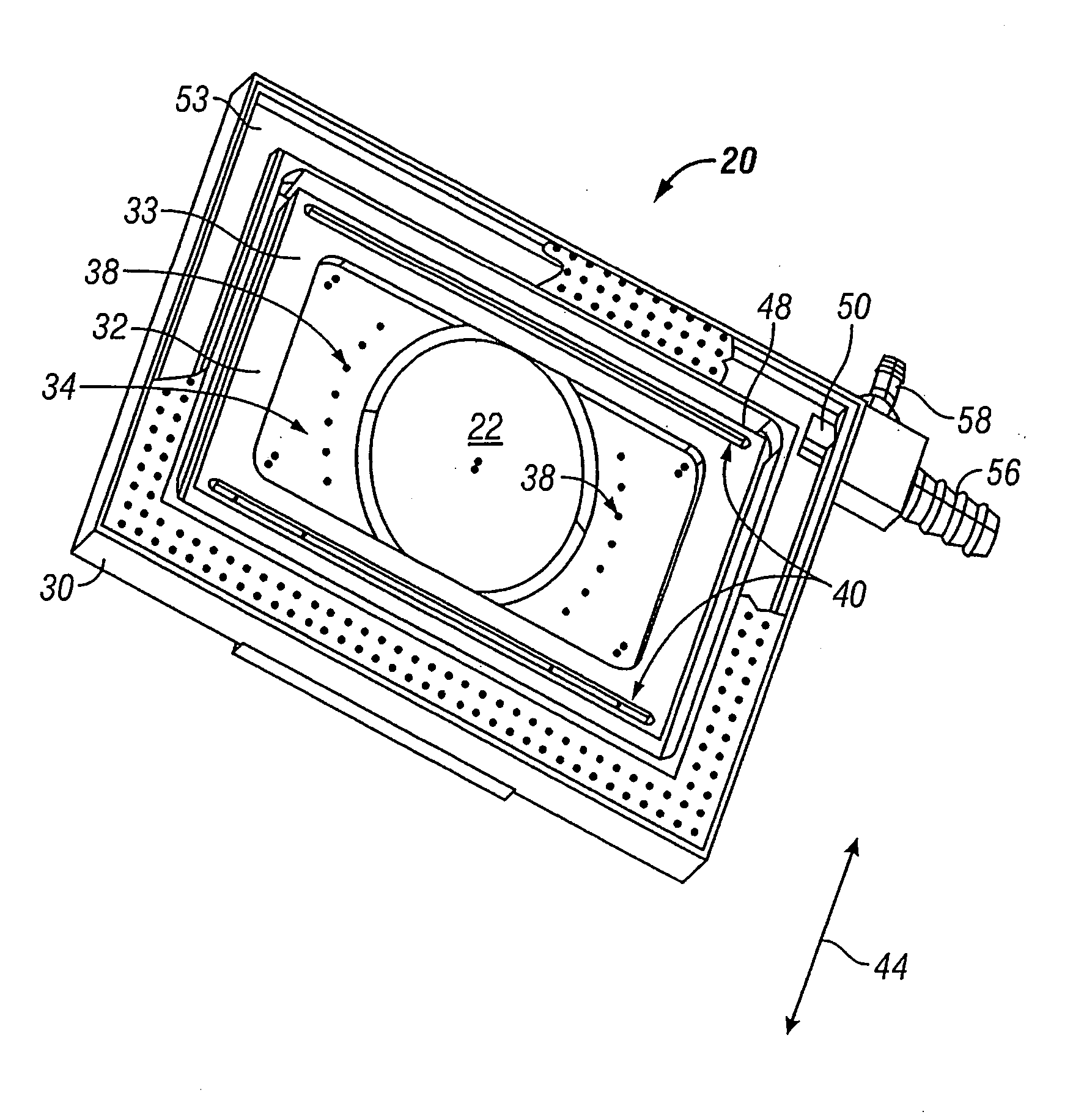
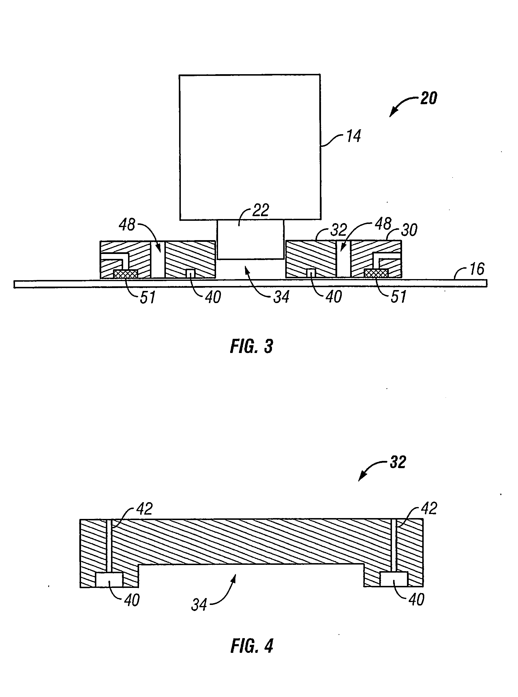
[0024]FIGS. 2 and 3 show the apparatus or nozzle 20 for delivery and recovery of the fluid between the final optical element 22 and the wafer 16 for immersion lithography. FIG. 2 shows the bottom perspective view of the nozzle 20, which includes an outer part 30 and an inner part 32. The inn...


PUM


Abstract

A lithographic projection apparatus projects a pattern from a patterning device onto a substrate using a projection system. The apparatus has a liquid supply system to supply a liquid to a space between the projection system and the substrate. The apparatus also has a fluid removal system including a chamber to hold liquid and having an open end adjacent to a volume in which fluid will be present. The open end removes, through a pressure differential across-the open end when liquid is present in the chamber, substantially only liquid from the volume when liquid in the volume is adjacent to the open end but not gas from the volume when gas in the volume is adjacent to the open end.

Description

CROSS-REFERENCES TO RELATED APPLICATIONS [0001] This is a divisional of U.S. patent application Ser. No. 11 / 362,833 filed Feb. 28, 2006, which in turn is a continuation of International Application No. PCT / US2004 / 022915 filed Jul. 16, 2004, which claims the benefit of U.S. Provisional Patent Application No. 60 / 500,312 filed Sep. 3, 2003, and U.S. Provisional Patent Application No. 60 / 541,329 filed Feb. 2, 2004. The disclosures of these applications are incorporated herein by reference in their entireties.BACKGROUND [0002] The invention relates generally to systems and methods for providing fluid for immersion lithography and, more particularly, for controlling the fluid flow and pressure to provide stable conditions for immersion lithography. [0003] An exposure apparatus is one type of precision assembly that is commonly used to transfer images from a reticle onto a semiconductor wafer during semiconductor processing. A typical exposure apparatus includes an illumination source, a r...

Claims


Application Information

Patent Timeline
IPC IPC(8): G03B27/42G02B21/00G03B27/52G03FG03F7/20
CPCG03F7/708G03F7/70341G03F7/70358G03F7/70858
Inventor POON, ALEX KA TIMKHO, LEONARD WAI FUNG
Owner NIKON CORP
Learn More