Heat treatment apparatus and method of calibrating the apparatus

Active Publication Date: 2007-08-23
TOKYO ELECTRON LTD
View PDF9 Cites 30 Cited by
  • Summary
  • Abstract
  • Description
  • Claims
  • Application Information

AI Technical Summary

Benefits of technology

[0010] The present invention has been made under the aforementioned circumstances, and an object of the present invention is to enable more precise temperat

Problems solved by technology

Consequently, for example, if the change in temperature during a heat treatment process coincides with the change in estimated temperature while the p

Method used


Image

  • Heat treatment apparatus and method of calibrating the apparatus
  • Heat treatment apparatus and method of calibrating the apparatus
  • Heat treatment apparatus and method of calibrating the apparatus

Examples


Embodiment Construction

[0048] An embodiment where a batch-type heat treatment apparatus of the present invention is applied to a vertical heat treatment apparatus will be described.

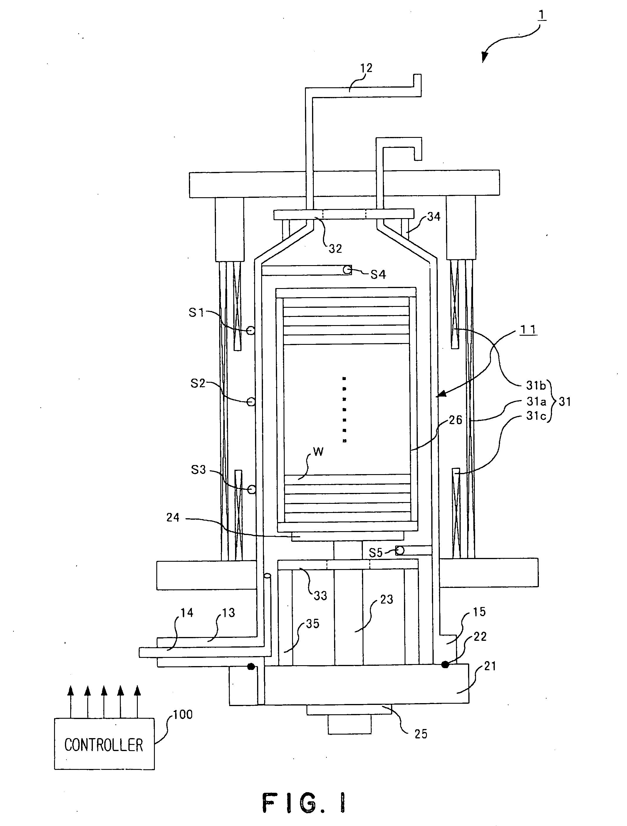
[0049] As shown in FIG. 1, a vertical type heat treatment apparatus 1 in this embodiment includes a processing vessel (reaction tube) 11. The processing vessel 11 is accommodates wafers W, which are process objects, to perform a designated heat treatment, for example, a CVD treatment, to the wafers W. The processing vessel 11 is formed of a heat-resistant and corrosion-resistant material, such as silica glass. The processing vessel 11 has a single-tube structure with its upper and lower ends being opened. The upper end of the single tube is narrowed to have a narrower diameter, forming an exhausting part 12. The exhausting part 12 is connected to a vacuum pump etc. through a not-shown exhaust pipe.

[0050] A gas introductory part (introduction port) 13 for introducing a processing gas and an inert gas into the processing vessel...


PUM

PropertyMeasurementUnit
Temperatureaaaaaaaaaa
Thermal propertiesaaaaaaaaaa

Abstract

The present invention provides precise temperature estimation in a heat treatment apparatus that estimates temperatures of process objects by using a thermal model and performs a heat treatment while performing a temperature control based on the estimated temperatures. The heat treatment apparatus 1 includes a processing vessel 11 accommodating plural wafers W, plural heaters 31 to 33 and plural temperature sensors S1 to S5, and stores the thermal model. The heat treatment apparatus 1 estimates temperatures of the wafers W based on outputs of the temperature sensors S1 to S5 by using the thermal model and controls the heaters 31 to 33 based on the estimated temperatures, applying a heat treatment to the wafers W. The thermal model for an individual apparatus is made by calibrating a standard thermal model designed for a standard apparatus. The standard model calibration is performed by heating an interior of the processing vessel 11, measuring the temperatures of the wafers W in the processing vessel 11, estimating the temperatures of the wafers W by using the thermal model, comparing the measured temperature and the estimated temperature, and calibrating the standard thermal model so that the measured temperature substantially coincide with the estimated temperature.

Description

TECHNICAL FIELD [0001] This invention relates to a calibrating method for a heat treatment apparatus that performs a heat treatment to a process object, such as a semiconductor wafer. Particularly, the invention relates to a method of calibrating a thermal model of a heat treatment apparatus that estimates the temperature of a process object accommodated in the apparatus by using the thermal model and performs a control based on the estimation result. BACKGROUND ART [0002] In a batch-type heat treating apparatus that performs a heat treatment, such as a film deposition process, an oxidation process or a diffusion process, to a number of semiconductor wafers collectively, process conditions, such as process temperature, process pressure and gas flow rate, are determined beforehand depending on the sort of a film to be formed and the film thickness, etc., and recipes describing the above process conditions are prepared. The operator selects a recipe corresponding to the sorts of a fil...

Claims


Application Information

Patent Timeline
IPC IPC(8): G01K15/00C23C16/52F27D19/00F27D21/00H01L21/00H01L21/205H01L21/22H01L21/324
CPCC23C16/46H01L21/67248H01L21/67103C23C16/52
Inventor PARK, YOUNGCHULKAWAMURA, KAZUHIROTAKENAGA, YUICHI
Owner TOKYO ELECTRON LTD
Why Eureka
Try Eureka