Optical power monitor

Inactive Publication Date: 2007-08-23
HITACHI METALS LTD
View PDF2 Cites 7 Cited by
  • Summary
  • Abstract
  • Description
  • Claims
  • Application Information

AI Technical Summary

Benefits of technology

[0012]An object of the present invention is to provide an optical power monitor having a reduced number of component parts, easy to assemble, capable of facilitating positioning for achieving improved optical coupling, and having a reduced size and a reduced manufacturing cost.

Problems solved by technology

Therefore, part of the optical signal is reflected by the open end surface of the optical fiber 35 to travel in the reverse direction in the optical fiber and interfere with the optical signal traveling forward, thus causing reflection loss.
This means difficulty in reducing the size and cost.

Method used


Image

  • Optical power monitor
  • Optical power monitor
  • Optical power monitor

Examples


example 1

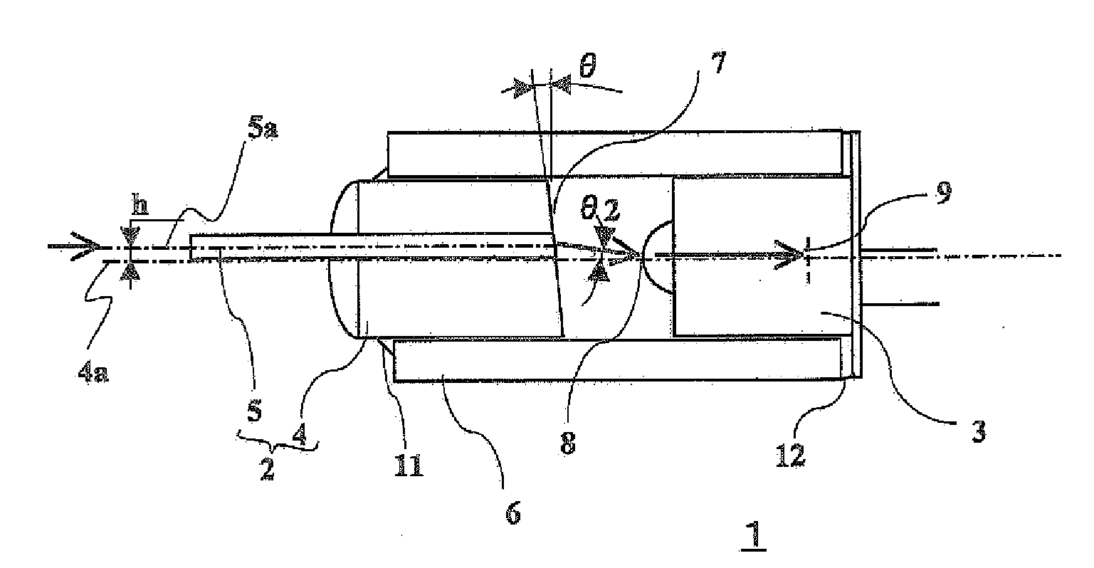
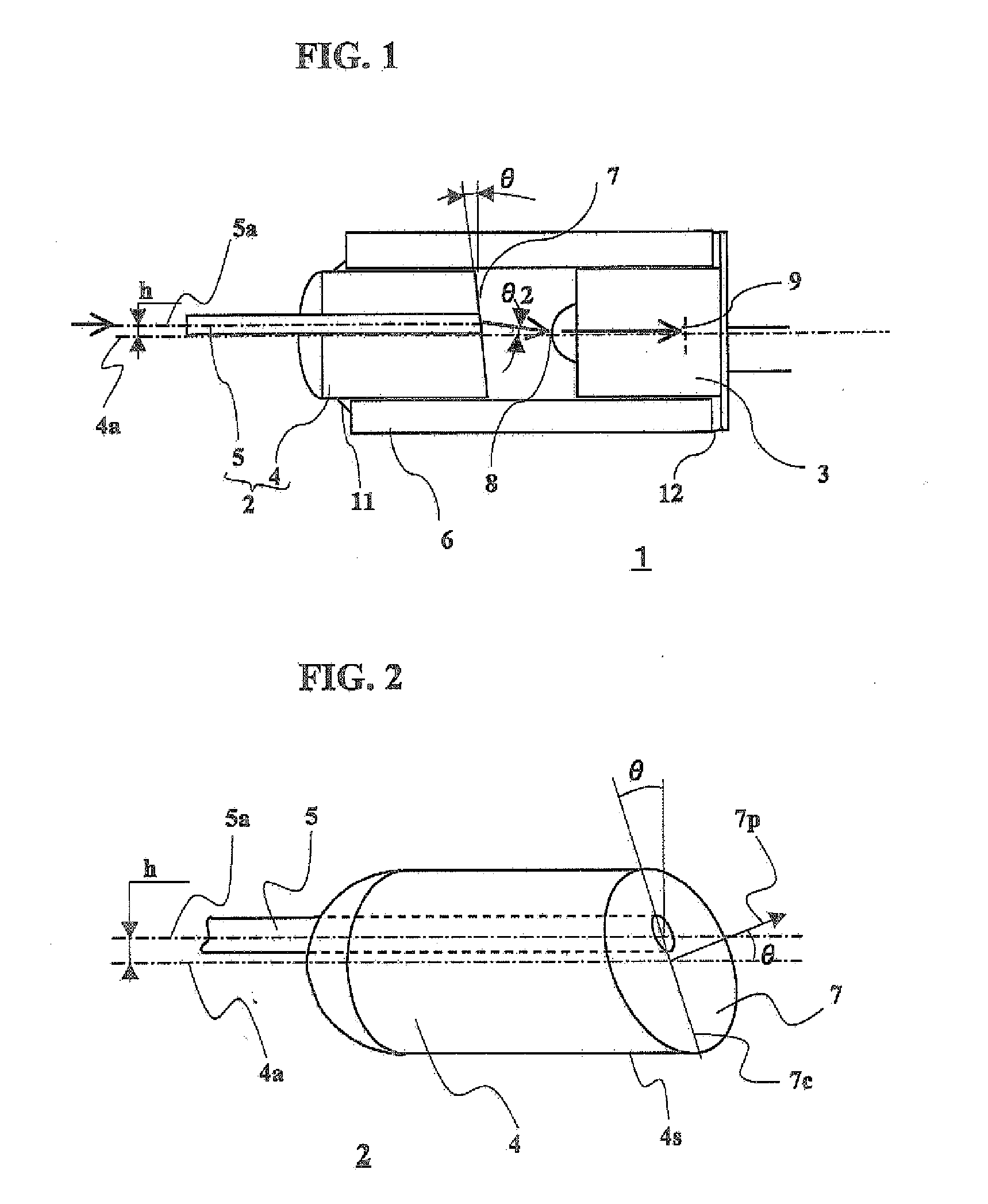
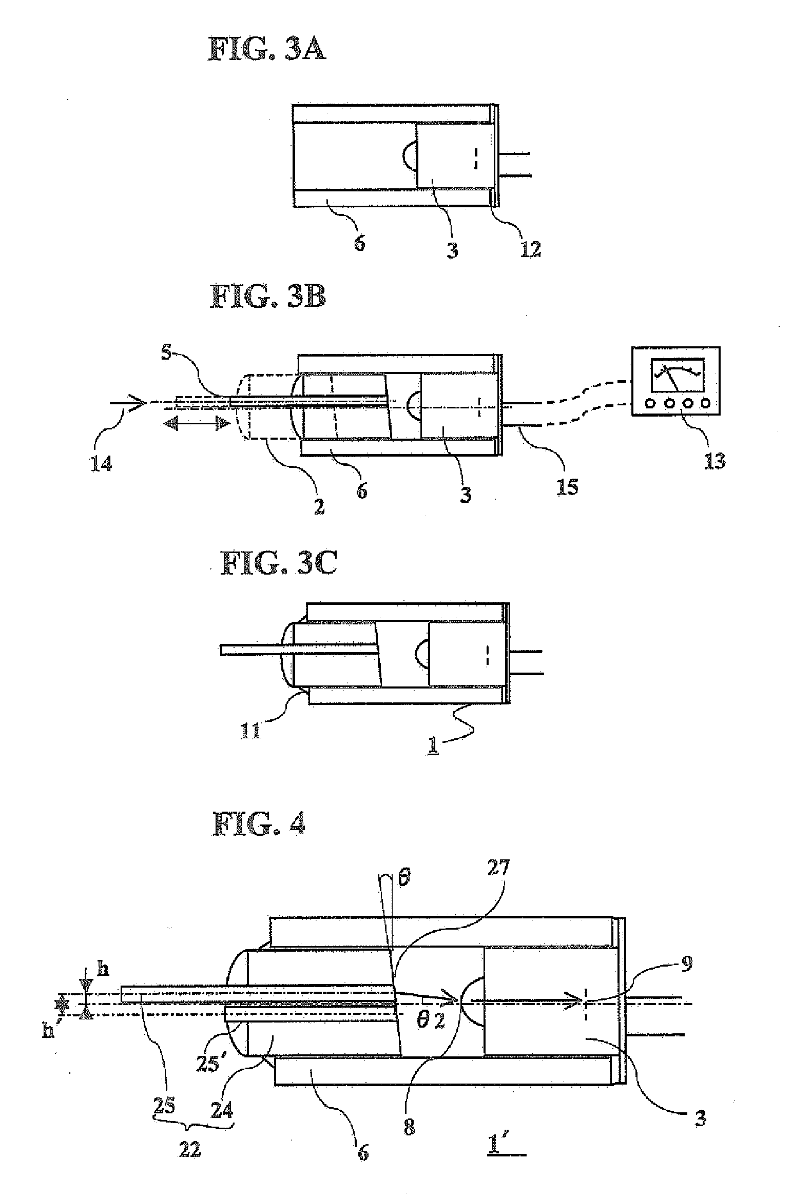
[0037]Detailed description of embodiments of the present invention, including a description of the structure of an optical power monitor in accordance with the present invention and a description of a method of assembling the optical power monitor, will be made. FIG. 1 is a sectional view of the structure of an optical power monitor according to the first embodiment of the present invention. FIG. 2 is a perspective view of a pigtail fiber. FIGS. 3A to 30 shows the process of assembling the optical power monitor.

[0038]Referring to FIG. 1, an optical power monitor 1 in accordance with the present invention has a pigtail fiber 2 and a photo diode 3 with a lens provided in a through-hole in a cylindrical tube 6 so that a light emission side end surface 7 of a columnar capillary 4 and the lens provided on the photo diode 3 are opposed to each other through a space of a predetermined length. The pigtail fiber 2 is formed by the columnar capillary 4 and an optical fiber 5. Referring to the...

example 2

[0042]FIG. 4 is a sectional view of an optical power monitor 1′ according to the second embodiment of the present invention. In this embodiment, a pigtail fiber 22′ having two optical fibers for use in a bi-directional optical power monitor 70 shown in FIG. 7 is used. The structure of the bidirectional optical power monitor 70 is such that a GRIN lens 71 with a tap film 72 is provided between the pigtail fiber and the photo diode with a lens in the above-described optical power monitor according to the first embodiment of the present invention. Light entering the optical power monitor through one optical fiber 25 in the two optical fibers 25 and 25′ is separated into reflected light (indicated by the double-dot-dash line) and transmitted light (indicated by the broken line) at the tap film 72 of the GRIN lens 71. The transmitted light enters the photo diode 3 to become an electrical signal, while the reflected light returns to the GRIN lens 71 and enters the other optical fiber 25′ ...


PUM


Abstract

An optical power monitor having a reduced number of component parts, easy to assemble, capable of facilitating positioning for achieving improved optical coupling, and having a reduced size and a reduced manufacturing cost. A pigtail fiber in which the center axis of an optical fiber is shifted from the center axis of the columnar capillary by 0.020 to 0.150 mm is used. The pigtail fiber and a photo diode are provided in a cylindrical tube with the pigtail fiber center axis and the photo diode center axis aligned with each other. The pigtail fiber and the photo diode can be adjusted to the optimum position in the cylindrical tube by adjustment in the longitudinal direction, thus advantageously simplifying the adjustment process in comparison with that in the conventional optical power monitor in which adjustments by movement in the radial direction, movement in the longitudinal direction and rotation about the center axis are made.

Description

BACKGROUND OF THE INVENTION[0001]1. Field of the Invention[0002]The present invention relates to an optical power monitor for measuring the intensity or energy of light in an optical fiber.[0003]2. Description of the Related Art[0004]With the rapid proliferation of the Internet, remarkable technical and quantitative developments have been made in the optical fiber communication market and optical communication networks are still presently being increased. With the increase in use of wavelength multiplex communication systems as one of large-capacity communication means, a need has arisen to handle several ten to several hundred wavelengths per system. There is a need to measure and monitor each of the energy of light of different wavelengths in operating a wavelength multiplex communication system. An optical power monitor is used for this purpose. A multiplicity of optical power monitors are used in a wavelength multiplex communication system. There is, therefore., a demand for red...

Claims


Application Information

Patent Timeline
IPC IPC(8): G02B6/36G02B6/42H01L31/10
CPCG02B6/4204G02B6/4207G02B6/4246G02B6/4233G02B6/4225H04B10/07G02B6/00H04B10/25
Inventor SUZUKI, MASARUUCHIDA, YOSHIAKIFURUICHI, SHINJI
Owner HITACHI METALS LTD
Why Eureka
Try Eureka