Multi-chamber spray cooling system

Inactive Publication Date: 2007-08-30
ISOTHERMAL SYST RES
View PDF6 Cites 39 Cited by
  • Summary
  • Abstract
  • Description
  • Claims
  • Application Information

AI Technical Summary

Benefits of technology

[0015] The present invention uses multiple global cooling chambers for providing liquid cooling to a plurality of electronic components. The global cooling chambers utilize a non-electrically conductive fluid which is in direct contact with the components to be cooled. The system provides very effective heat transfer rates, environmental isolation of the electronics components and can be deployed in a wide range of applications. Multiple global cooling chambers allows for the hot swapping of cards

Problems solved by technology

Water must be kept separate from the electronics since it would obviously short out the circuits and cause irreparable harm to the electronic systems and components.
A significant challenge in using dielectric fluids within closed loop cooling systems is that they typically have poor heat transfer properties.
The result is that it can be difficult to get heat into dielectric fluids.
Liquid absorbs heat and transforms into vapor which requires substantial amounts of energy.
One problem with prior art global cooling systems is that because the electronics reside within a single chamber, the entire computing system must be shut down in order to provide service and maintenance of a single board within.
Although the maintenance and service requirements may be perfectly acceptable for global c

Method used


Image

  • Multi-chamber spray cooling system
  • Multi-chamber spray cooling system
  • Multi-chamber spray cooling system

Examples


Embodiment Construction

[0032] Many of the fastening and fluid components utilized and described in this invention are widely known and used in the field of the invention, and their exact nature or type is not necessary for a person of ordinary skill in the art or science to understand the invention; therefore they will not be discussed in detail.

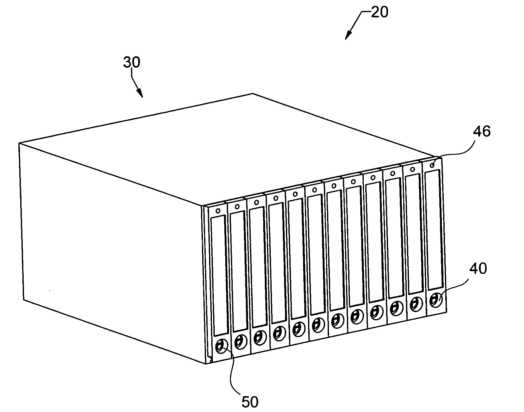
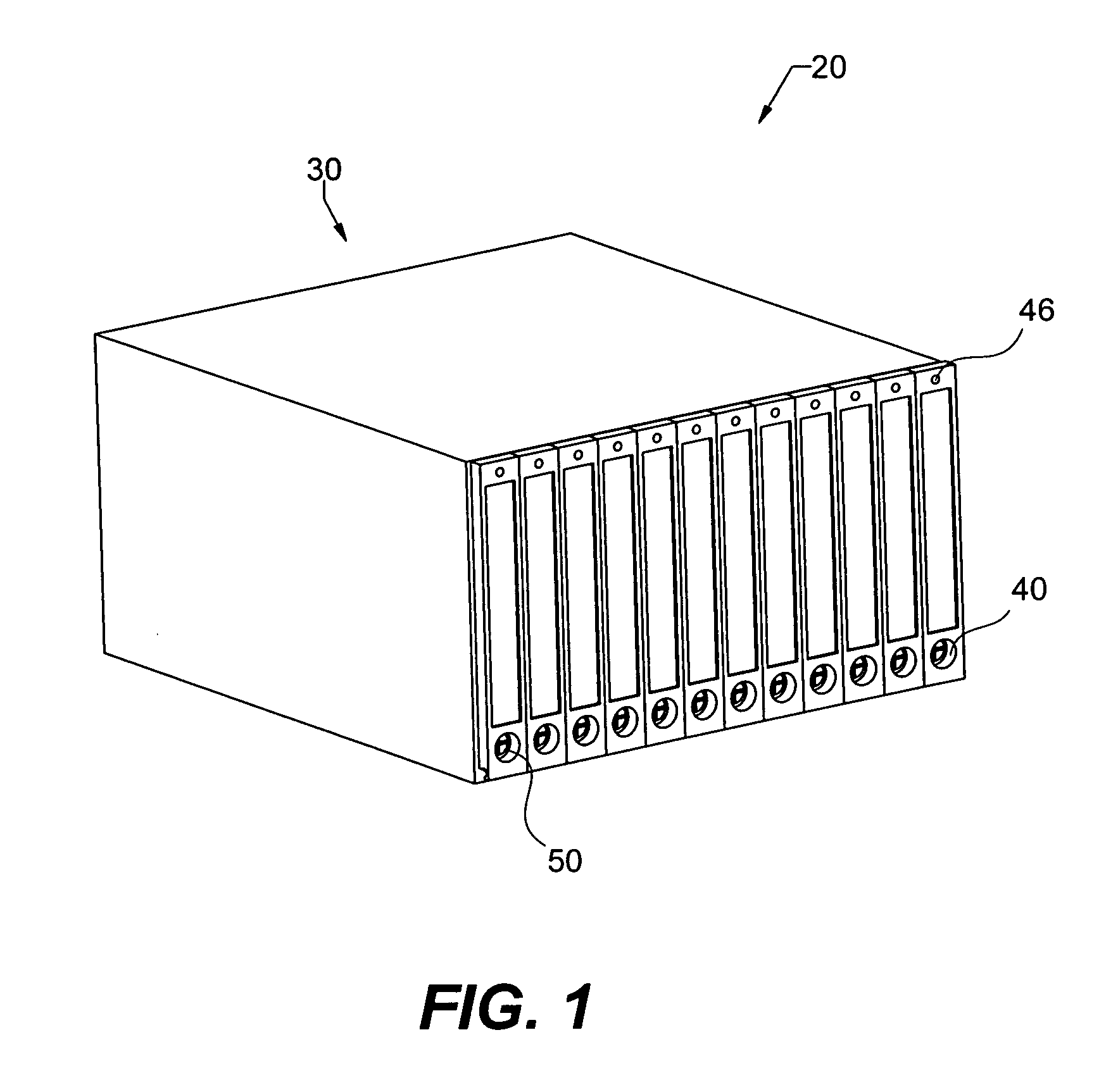
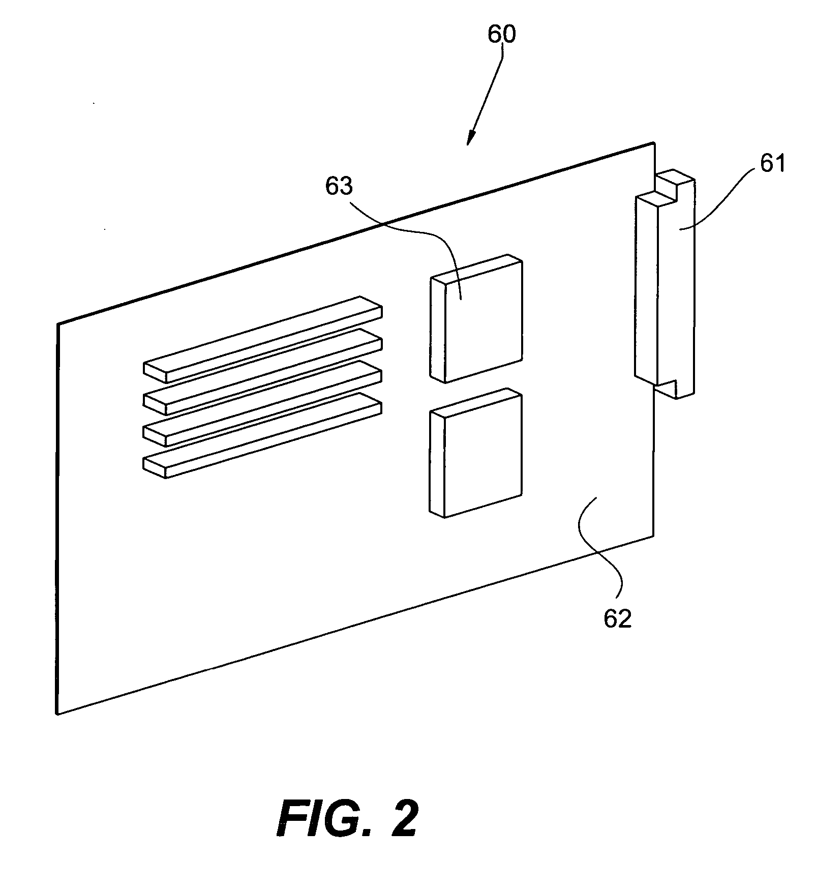
[0033] As used herein, the term “card” generally refers to an electronic system that may produce heat. A card may include a blade server, a networking device, or any type of computer sub-system. In addition, the card may be a power device, such as a power supply, or a conversion device such as used for converting alternating current to direct current, or vice-versa. The present invention should not be construed to be limited to any one type of card system.

[0034] As part of the description of the preferred embodiment, the present invention is described for use with the dielectric fluid Fluorinert (a trademark of 3M). Fluorinert is brand that represents a family o...


PUM


Abstract

The present invention uses multiple global cooling chambers for providing liquid cooling to a plurality of electronic components. The global cooling chambers utilize a non-electrically conductive fluid which is in direct contact with the components to be cooled. The system provides very effective heat transfer rates, environmental isolation of the electronics components and can be deployed in a wide range of applications. Multiple global cooling chambers allows for the hot swapping of cards during operation of the system.

Description

CROSS REFERENCE TO RELATED APPLICATION [0001] The present invention is a continuation-in-part of U.S. patent application Ser. No. 10 / 648,774 filed Aug. 18, 2003 entitled “Wet-Dry Thermal Management System”. The Ser. No. 10 / 648,744 patent application is incorporated herein by this reference.STATEMENT REGARDING FEDERALLY SPONSORED R&D [0002] Not applicable to this application. TECHNICAL FIELD [0003] This invention relates to a liquid cooling system, and more particularly to a direct liquid cooling system that utilizes a chassis that contains a plurality of individually sealed chambers. BACKGROUND OF THE INVENTION [0004] Liquid cooling is becoming widely understood in the field of electronics cooling. Rather than use air to cool heat producing components, liquid is used to absorb and transport the heat. Liquids are typically much more efficient than air as a heat transfer fluid since they have considerably higher thermal conductivities, specific heat capacities and provide the opportun...

Claims


Application Information

Patent Timeline
IPC IPC(8): F25D23/12F28D5/00F25D17/06F26B19/00F26B25/06H05K7/14H05K7/20
CPCH05K7/20345H05K7/1425F28D15/0266F28D5/00
Inventor KNIGHT, PAUL A.TILTON, CHARLES L.
Owner ISOTHERMAL SYST RES
Why Eureka
Try Eureka