Method And Device For Removing Liquids From The Surface Of A Strip

a technology of moving strips and liquids, which is applied in the direction of work treatment devices, electrostatic cleaning, cleaning processes and apparatuses, etc., can solve the problems of limiting the removal method of lubricant remains, unusable displacement of individual turns in the axial direction of the coil, and small remains of liquids previously used on the surface of the strip

Inactive Publication Date: 2007-08-30
BETRIEBSFORSCHUNGSINSTITUT VDEH INSTITUT FUR ANGEWANDTE FORSCHUNG
View PDF4 Cites 4 Cited by
  • Summary
  • Abstract
  • Description
  • Claims
  • Application Information

AI Technical Summary

Benefits of technology

[0008] The excitation of the liquid is preferably performed in such a way that contiguous areas of liquid, for example a liquid film, are completely excited to undergo oscillation. In this case, the excitation and the further treatment of the film, for example removal in the manner of blowing / suction in a preferably laminar flow, can be performed in such a way that the liquid film is preserved, or at least only divided into large parts, for example parts with an extent of at least twice the film thickness, with particular preference parts with a much greater extent, such as for example 3 to at least 10 times the film thickness. In a preferred embodiment, an excitation which prevents the formation of liquid aerosols is set. This allows the effect to be achieved that the liquid removed by suction or blowing, for example in the form of parts of a large area or spherical parts can be easily recovered. As a result, the advantage that is made possible by the method according to the invention even other than within this preferred embodiment, that of the recovery of expensive liquids, for example oils in rolling mills, is achieved particularly easily.
[0009] This invention is used in particular for the removal of liquids from moving strips, and here in particular in rolling trains. The basic concept according to the invention can also be applied, however, to stationary strip surfaces. The liquid to be removed is, in particular, an oil or an emulsion which has been applied to the strip during the rolling operation as a coolant and / or lubricant. The invention is used with particular preference for detaching liquid films which take up virtually the full width of the strip, since the method according to the invention is suitable for detaching these large-area liquid films efficiently from the strip.

Problems solved by technology

If these remains are not removed before the strip is formed into a coil, they form a lubricating film between the individual turns, possibly leading to undesired displacement of the individual turns in the axial direction of the coil.
Furthermore, only very small remains of the liquids previously used may be present on the surface of the strip for the further treatment of the strips.
The running speed of the strip thereby often restricts the manner of removal of the lubricant remains.
Devices of this type are very energy-intensive.
The high flow velocities also lead to the problem of a high noise level.

Method used


Image

  • Method And Device For Removing Liquids From The Surface Of A Strip
  • Method And Device For Removing Liquids From The Surface Of A Strip
  • Method And Device For Removing Liquids From The Surface Of A Strip

Examples


Embodiment Construction

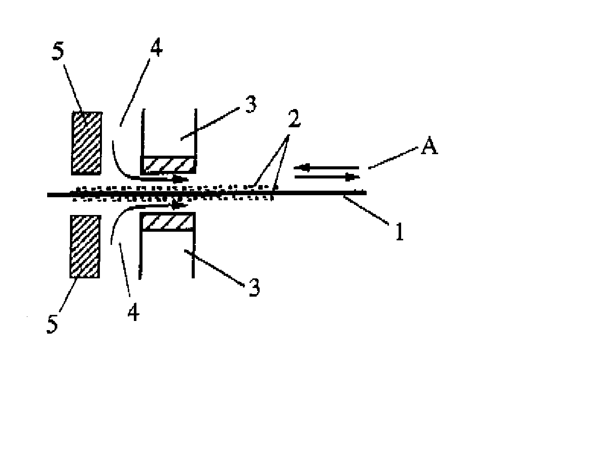
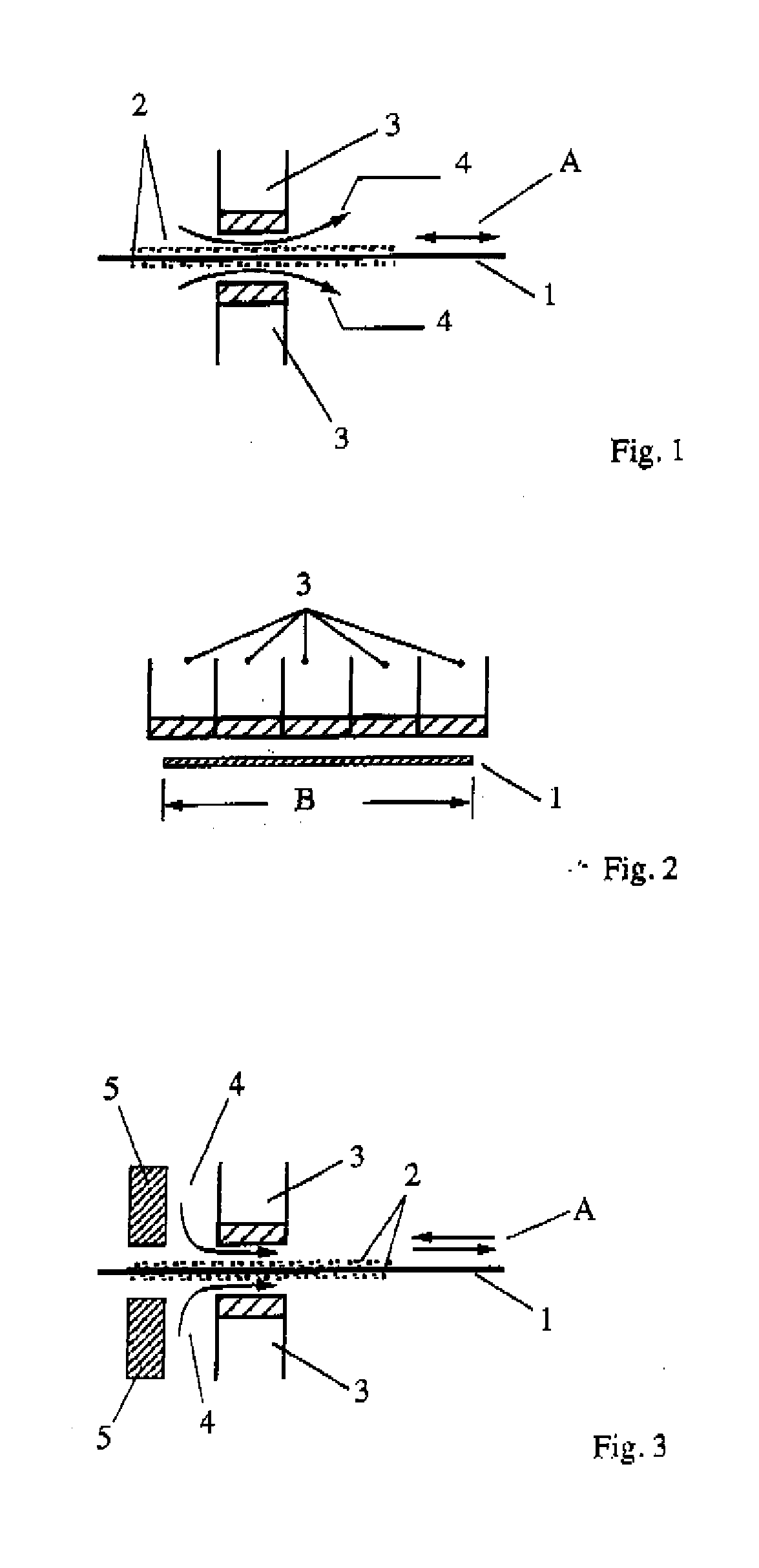
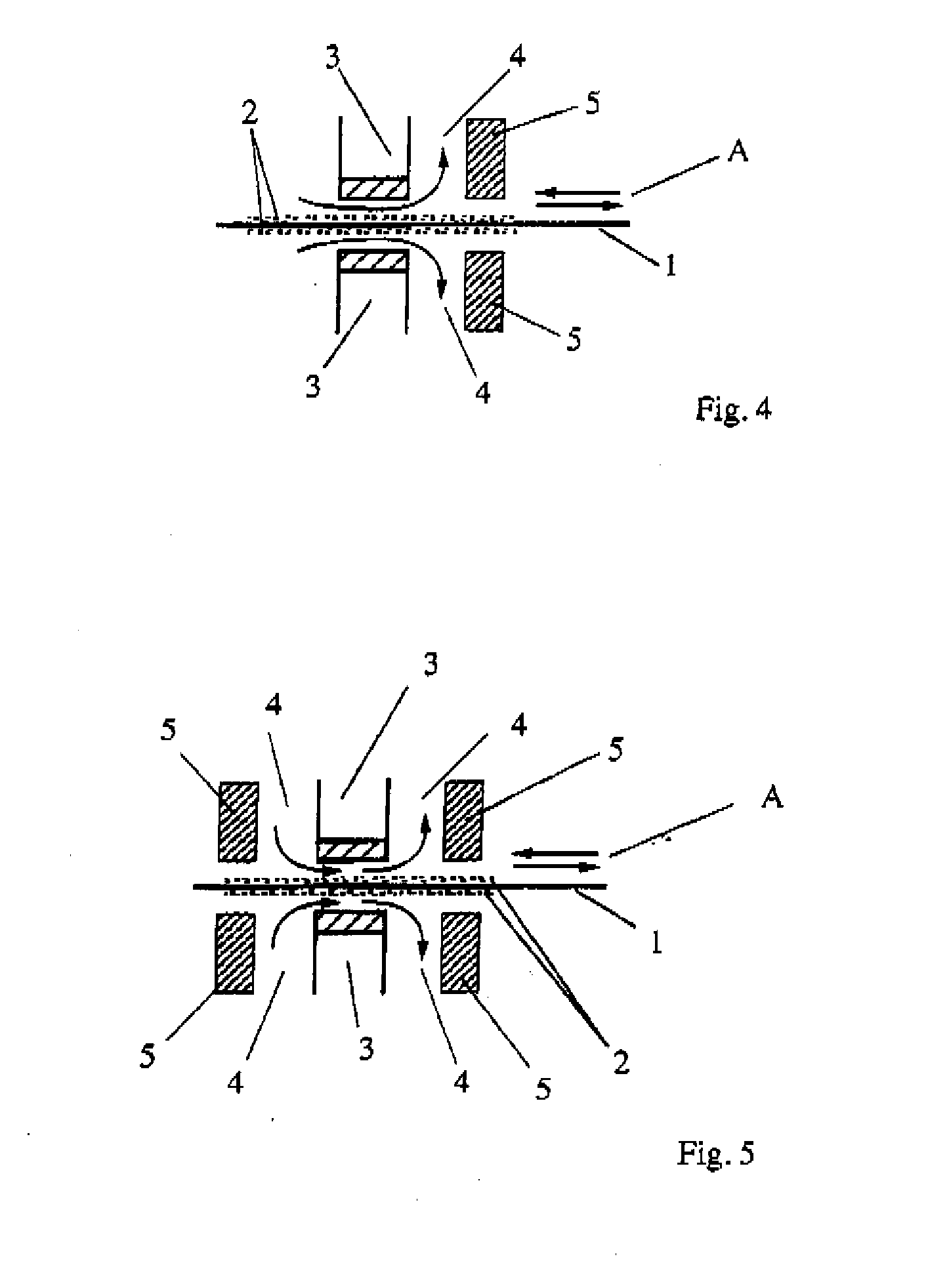
[0042]FIG. 1 shows a moving strip 1, on the upper side and underside of which a liquid 2, for example lubricant, attaches. Respectively fitted above and below the strip 1 is a transducer 3. An air stream 4 is respectively generated by blowing nozzles (not represented) between the free surface of the liquid 2 and the transducer 3. The directional arrows A indicate that the air stream 4 may be directed both with and counter to the strip running direction. FIG. 2 shows that the transducers 3 arranged above the strip 1 are arranged next to one another in such a way that transducers extend over the entire width B of the strip.

[0043] For removing the liquid 2 from the surface of the strip 1, sound waves are emitted into the air stream 4 by the transducers 3, which are formed for example as piezoelectric ultrasound-transmitting probes. As a result, the air stream 4 is excited to undergo an oscillation. The air stream 4 transfers this excitation oscillation to the liquid 2 and excites the ...


PUM

PropertyMeasurementUnit
angleaaaaaaaaaa
thicknessesaaaaaaaaaa
thicknessaaaaaaaaaa

Abstract

A method for removing liquids from the surface of a strip, characterized in that the liquid is excited in such a way that it oscillates. The invention is based on the recognition that the root of the problem of removing liquids from the surface of a strip lies in the adhesion forces and that these adhesion forces can be overcome by exciting the liquid in such a way that it oscillates. Its oscillation causes the liquid to detach itself from the surface of the strip and it can then be easily carried away, for example by suction by means of low pressure, blowing or stripping by means of a stripper.

Description

BACKGROUND OF THE INVENTION [0001] The invention relates to a method and a device for removing liquids from the surface of a moving strip. Methods and devices of this type are used in particular in the case of strip processing machines, such as roiling stands for example. [0002] In strip processing processes, it is customary to apply lubricants to the strip, in order for example to assist the deforming process during the rolling operation and in order to dissipate deformation heat and fragments of strip. Remains of these lubricants stay attached to the strip after the rolling operation as residues. If these remains are not removed before the strip is formed into a coil, they form a lubricating film between the individual turns, possibly leading to undesired displacement of the individual turns in the axial direction of the coil. Furthermore, only very small remains of the liquids previously used may be present on the surface of the strip for the further treatment of the strips. [000...

Claims


Application Information

Patent Timeline
Patent Type & Authority Applications(United States)
IPC IPC(8): B08B3/00B08B3/12B08B6/00B08B3/04B08B5/00B08B7/02B21B45/02
CPCB08B3/041B21B45/0284B08B7/02B08B5/00
Inventor MUCKE, GERTCOEN, GUNTHERGORGELS, FRANK
Owner BETRIEBSFORSCHUNGSINSTITUT VDEH INSTITUT FUR ANGEWANDTE FORSCHUNG
Why Eureka
Try Eureka