
Decanter stopper with a vacuum pressure indicator

a vacuum pressure indicator and stopper technology, applied in the field of wine systems and methods, can solve the problems of wine deterioration, off-flavor of unconsumed wine, and the quality of non-carbonated soft drinks may deteriora

Inactive Publication Date: 2007-08-30
METROKANE
View PDF11 Cites 18 Cited by
  • Summary
  • Abstract
  • Description
  • Claims
  • Application Information

AI Technical Summary

Benefits of technology

"The present invention provides a stopper system for preserving beverages in a vessel by airtight sealing the vessel mouth and maintaining a vacuum pressure within the vessel. The system includes a valve assembly and a pressure indicator for measuring vacuum pressure. The system can be easily manufactured and used with commonly available materials. The technical effects of the invention include preventing deterioration of unconsumed beverages due to oxidation and other chemical reactions, indicating a decompressurization of the decanter, and providing a means for maintaining a vacuum pressure within the vessel."

Problems solved by technology

Exposure of the wine to air for longer periods, such as six hours or more, however, tends to deteriorate the wine.
In particular, oxygen present in the air contacting the unconsumed wine in the decanter will oxidize the wine, resulting in off-flavors in the unconsumed wine.
Similarly, the quality of non-carbonated soft drinks may deteriorate upon exposure to air due to oxidation or other chemical reactions.
For one, a seal formed by the stopper valve is generally not very stable and prone to failure due to natural and mechanical causes.
For example, the presence of liquid or dust particles on the valve may result in a leaky seal, decompressurization of the bottle, and inadvertent penetration of air into the bottle.
Furthermore, repeated use of the stopper as well as the pressure differential across thereof may result in degradation of its elastic properties.
Should the seal fail due to these or other reasons and allow air to enter the bottle, the wine will deteriorate due to oxidation or other chemical reactions.
The system however provides no suitable means for detecting the failure of the seal and the resulted decompressurization of the bottle.
Such failure, if remained undiscovered, will allow deterioration of the wine to progress undetected.
Another shortcoming of the prior art pump systems is that the provided stoppers are usually configured to only fit the standard-size wine bottles and thus are not suitable for decanters, which typically have much wider neck openings.

Method used


Image

  • Decanter stopper with a vacuum pressure indicator
  • Decanter stopper with a vacuum pressure indicator
  • Decanter stopper with a vacuum pressure indicator

Examples


Embodiment Construction

[0021] In the following description of the various embodiments of the present invention, reference is made to the accompanying drawings that form a part hereof, and in which is shown by way of illustration various embodiments of the present invention. It is to be understood that the scope of the present invention is not limited by the following description and by the accompanying drawings.

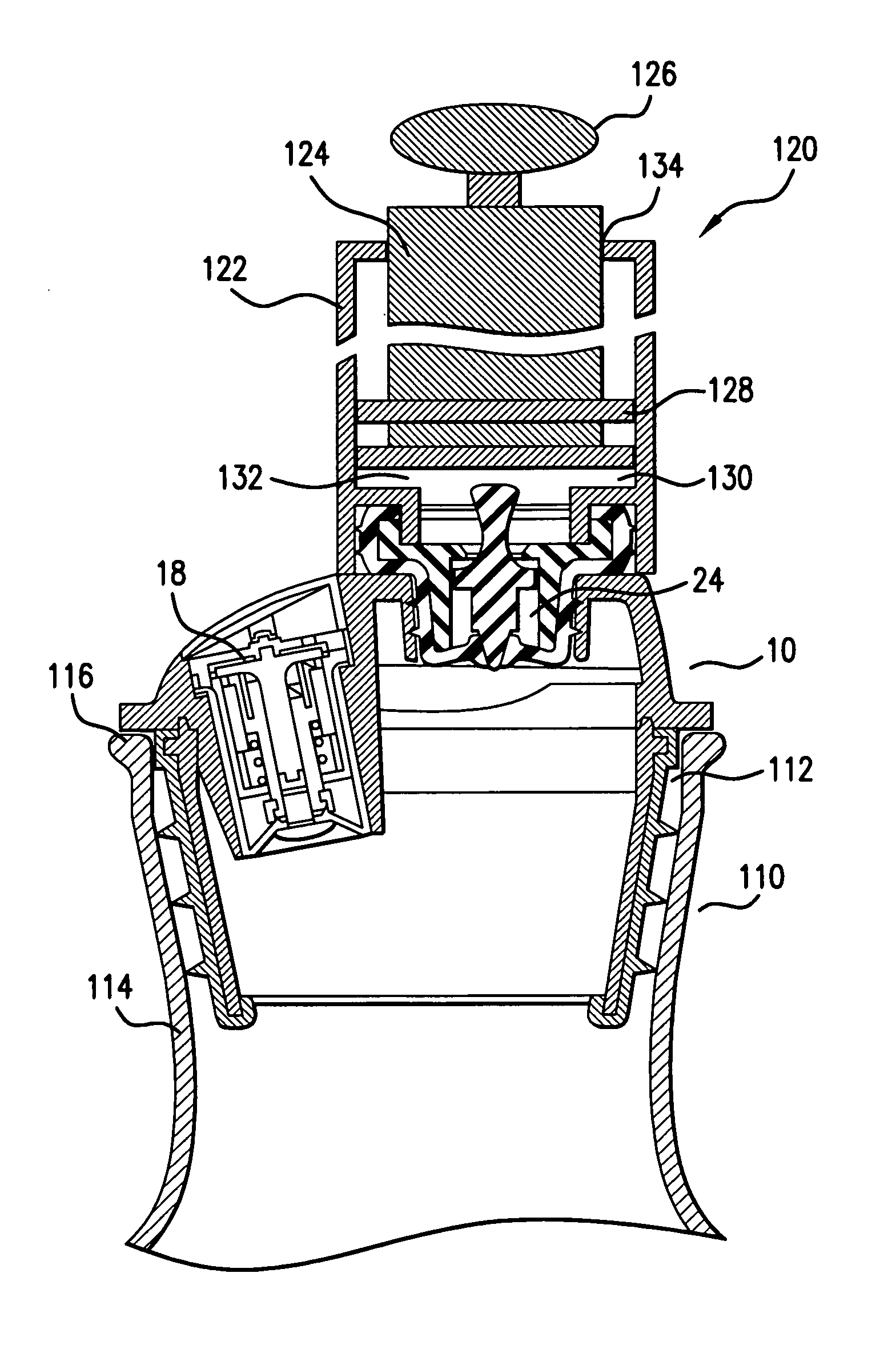
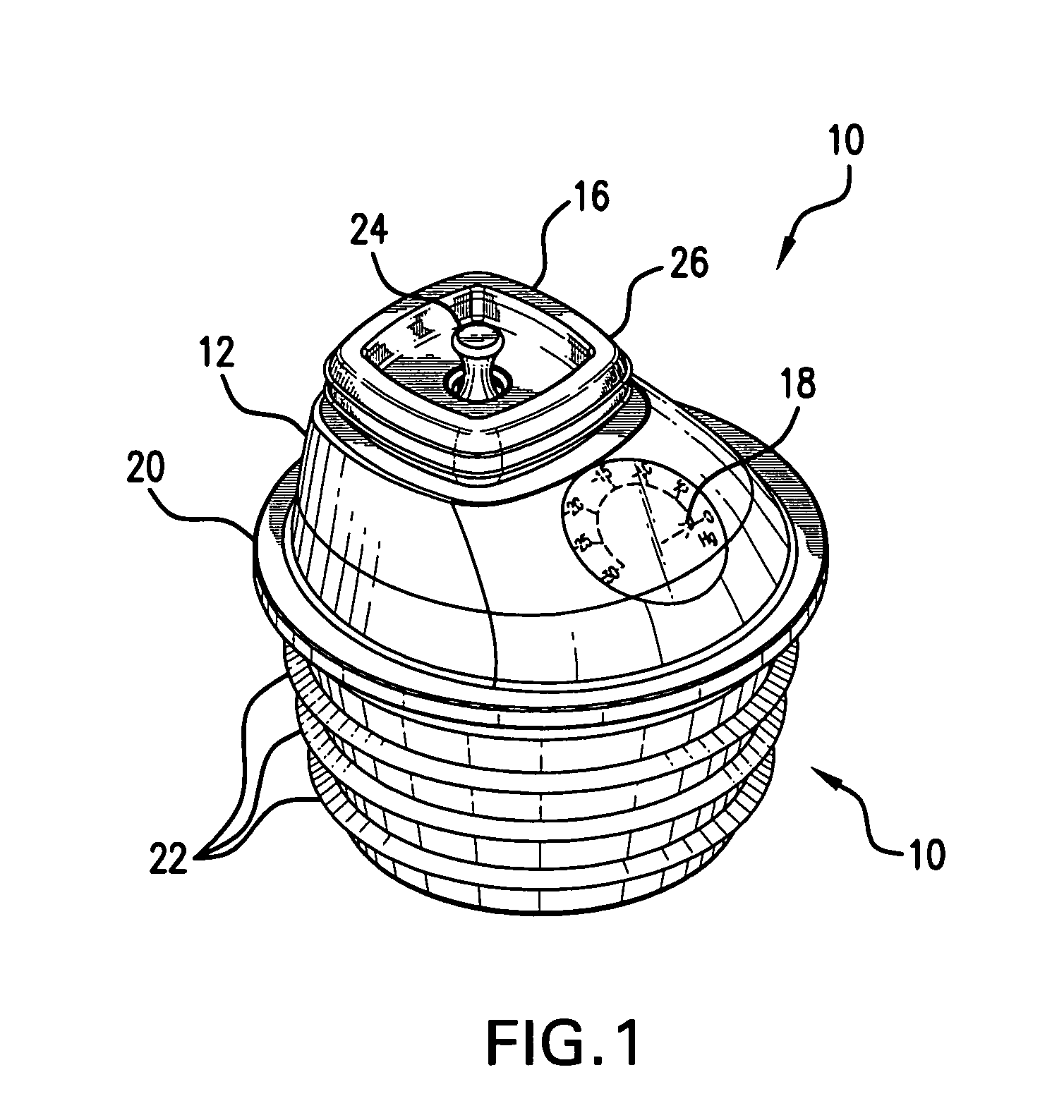
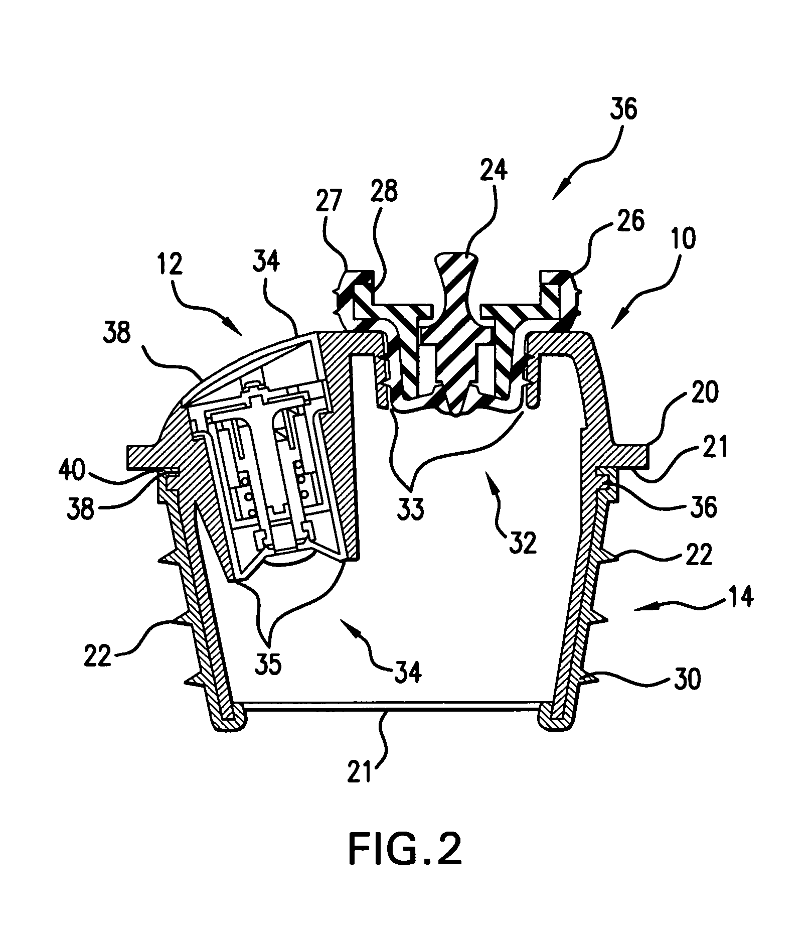
[0022]FIGS. 1 and 2 illustrate an elevated and section views, respectively, of a stopper for a decanter in accordance with an exemplary embodiment the present invention. The stopper 10 comprises a one-piece, integral, cylindrical body having an upper enclosed portion 12 and lower portion 14, which may be defined by a circumferential flange 20 extending radially outward. The enclosed upper portion 12 of the stopper 10 may comprise a semi-spherical body having two openings 32 and 34. The lower portion 14 is adapted to be inserted into the mouth 112 of the decanter 110 and thus may have an outside di...


PUM


Abstract

Disclosed are systems and methods for preserving wine in a decanter. The system comprises a stopper adapted for engaging and airtight sealing the mouth of the decanter; the stopper comprises a valve assembly operable to draw and maintain a pressure differential within the decanter and a pressure indicator operable to indicate vacuum pressure within the vessel. The system further comprises a pump operable to engage the valve assembly and to draw gas from within the decanter to an external atmosphere.

Description

FIELD OF THE INVENTION [0001] The present invention relates generally to the systems and methods for preserving wine and more specifically to a decanter stopper having means for drawing and maintaining a vacuum within the decanter and a vacuum pressure indicator. BACKGROUND OF THE INVENTION [0002] A decanter is a vessel used for holding the results of decantation where a liquid beverage from another vessel is poured into the decanter and the sedimentary remainder of the liquid is left in the original vessel. Decanters are commonly used to store various alcoholic and non-alcoholic beverages including wines, juices and the like. Decanters come in various shapes and sized and may be ornate and suitable for serving the liquid beverages. A decanter usually comprises a vessel having a spherical body and a narrow, elongated neck. Decanters often come with stoppered lids, which, in addition to preventing accidental spilling of the liquid from the vessel, prevent excessive exposure of the be...

Claims


Application Information

Patent Timeline
Patent Type & Authority Applications(United States)
IPC IPC(8): B65B31/04
CPCB65D81/2038
Inventor LARIMER, BOBKILDUFF, EDWARD
Owner METROKANE
Learn More