Vehicle control apparatus and vehicle control method

a technology for controlling apparatus and vehicles, applied in the direction of machines/engines, braking components, anti-theft devices, etc., can solve problems such as vibration of vehicles, and achieve the effect of reducing vibration of vehicles

Inactive Publication Date: 2007-08-30
TOYOTA JIDOSHA KK
View PDF6 Cites 19 Cited by
  • Summary
  • Abstract
  • Description
  • Claims
  • Application Information

AI Technical Summary

Benefits of technology

[0011]The invention provides a vehicle control apparatus and method which restrain vibrations of the vehicle when a drive source is started while the vehicle is at a stop with a vehicle non-run position of a transmission being selected.

Problems solved by technology

In such a case, the startup of the drive source may cause vibration of the vehicle.

Method used


Image

  • Vehicle control apparatus and vehicle control method
  • Vehicle control apparatus and vehicle control method
  • Vehicle control apparatus and vehicle control method

Examples


first embodiment

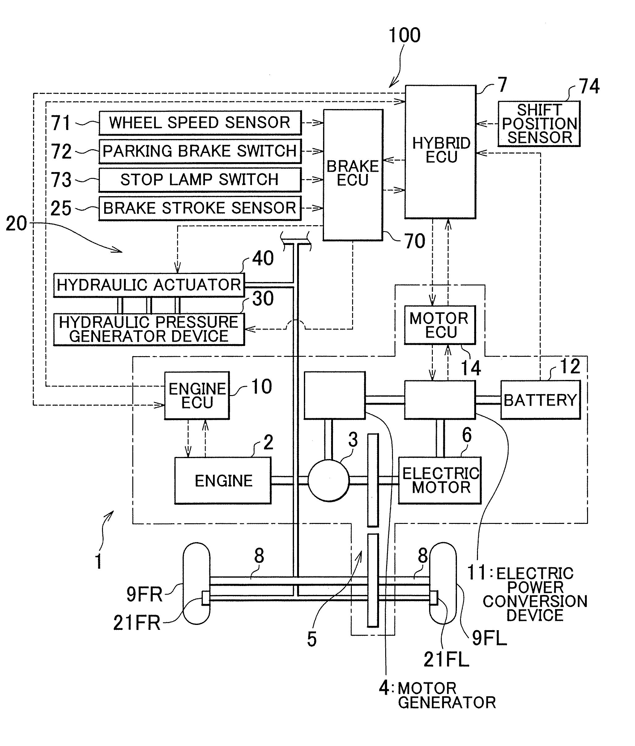
[0031]FIG. 1 is a schematic construction diagram showing a vehicle to which a vehicle control apparatus in accordance with an embodiment of the invention is applied. A vehicle 1 shown in FIG. 1 is constructed as a vehicle adopting a so-called hybrid system, and comprises: an engine 2 as a drive source, a three-axis power splitting mechanism 3 connected to a crankshaft that is an output shaft of the engine 2, a motor generator 4 connected to the power splitting mechanism 3 and being capable of generating electric power, an electric motor 6 connected to the power splitting mechanism 3 via a transmission 5, and a hybrid-purpose electronic control unit (hereinafter, referred to as “hybrid ECU” with the electronic control unit being always termed “ECU”) 7 that controls the entire drive system of the vehicle 1. A front right wheel 9FR and a front left wheel 9FL as drive wheels of the vehicle 1 are linked to the transmission 5 via a drive shaft 8.

[0032]The engine 2 is, for example, an inte...

second embodiment

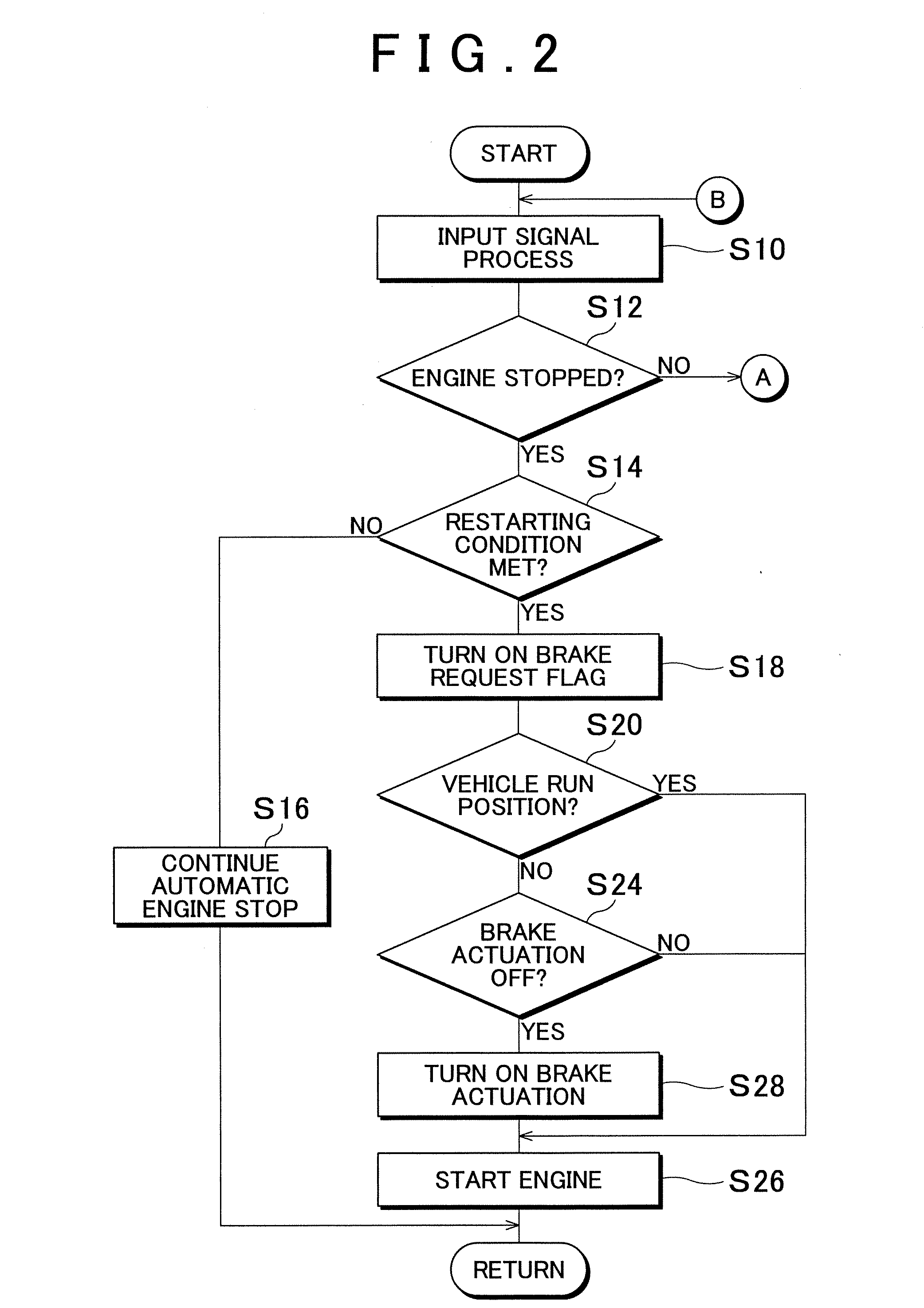
[0064]FIG. 5 is a flowchart illustrating a brake actuation control in accordance with a second embodiment. With reference to FIG. 5, the brake actuation control performed when the restarted engine 2 is stopped will be described.

[0065]If it is determined at S12 in FIG. 12 that the engine 2 is not stopped (NO at S12), the hybrid ECU 7 determines whether or not a condition for stopping the engine 2 is met (S40), on the basis of a result obtained at S10 by processing various input signals that indicate states of the vehicle. In this embodiment, it is determined whether or not the state of charge of the battery 12 is greater than or equal to a predetermined control value. Specifically, the SOC value indicating the state of charge is detected. On the basis of the information, the hybrid ECU 7 determines whether or not to stop the engine 2.

[0066]If the SOC value is less than the predetermined control value, it is determined that the condition for stopping the engine 2 is not met (NO at S40...

third embodiment

[0073]FIG. 7 is a flowchart illustrating a brake actuation control in accordance with the third embodiment. With reference to FIG. 7, the brake actuation control performed when the restarted engine 2 stops. Incidentally, contents of the third embodiment that overlap with those of the first embodiment or the second embodiment will not be described in detail again.

[0074]If at S12 in FIG. 2 it is determined that the engine 2 is not stopped (NO at S12), the hybrid ECU 7 determines whether or not a condition for stopping the engine 2 is met (S60), on the basis of a result obtained at S10 by processing various input signals that indicate states of the vehicle. In this embodiment, the hybrid ECU 7 determines whether or not the state of charge of the battery 12 is greater than or equal to a predetermined control value.

[0075]If the SOC value is less than the predetermined control value, it is determined that the condition for stopping the engine 2 is not met (NO at S60), and various input si...


PUM


Abstract

In a vehicle control apparatus, a hybrid ECU automatically stops and starts an engine if a predetermined condition is met while the vehicle is stopped. A brake ECU controls the braking force applied to wheels. A hybrid ECU controls the brake ECU so that braking force is applied to the wheels at the time of startup of the engine if while the vehicle is stopped, the vehicle run position is not selected as a shift position of the transmission. This restrains vibration of the vehicle at the time of startup of the engine.

Description

INCORPORATION BY REFERENCE[0001]The disclosure of Japanese Patent Application No. 2006-050678 filed on Feb. 27, 2006 including the specification, drawings and abstract is incorporated herein by reference in its entirety.BACKGROUND OF THE INVENTION[0002]1. Field of the Invention[0003]The invention relates to a vehicle control apparatus and method for controlling operation of a vehicle, more particularly, a hybrid vehicle combining an electric motor and an internal combustion engine.[0004]2. Description of the Related Art[0005]A so-called hybrid system in which an electric motor and an internal combustion engine as drive sources of a vehicle are combined is conventionally known. In the hybrid system, a control of stopping the driving of the engine under a predetermined condition in order to achieve improved fuel economy and reduced exhaust gas is sometimes performed. From such a situation where the engine is stopped, a control of restarting the driving of the engine under a predetermi...

Claims


Application Information

Patent Timeline
Patent Type & Authority Applications(United States)
IPC IPC(8): B60T13/74B60K6/445B60T7/12F02N11/04F02N11/08F02N11/10F02N15/00
CPCB60K1/02Y02T10/7275B60K6/547B60T1/10B60T13/665B60W10/06B60W10/184B60W20/00Y02T10/6239Y02T10/7077Y02T10/7044Y02T10/7005Y02T10/705Y02T10/7241Y02T10/6217Y02T10/642B60L11/123B60L11/14B60L11/1861B60L15/20B60L2210/40B60L2240/421B60L2240/423B60L2240/441B60L2240/443B60L2240/461B60L2240/486B60L2250/12B60L2250/26B60K6/445B60L50/16B60L50/61B60L58/12Y02T10/62Y02T10/64Y02T10/70Y02T10/7072Y02T10/72
Inventor SAKAI, AKIRA
Owner TOYOTA JIDOSHA KK
Why Eureka
Try Eureka