Organic electroluminescence display device

a display device and organic technology, applied in the direction of discharge tube luminescnet screens, discharge tube/lamp details, electric discharge lamps, etc., can solve the problems of high cost of resin molds for manufacturing resin molds, affecting the cooling efficiency of the device, and inevitably deteriorating adhesives, etc., to achieve the effect of increasing heat radiation effects, increasing impact strength and static load strength, and increasing cooling efficiency

Active Publication Date: 2007-08-30
HITACHI DISPLAYS +1
View PDF3 Cites 11 Cited by
  • Summary
  • Abstract
  • Description
  • Claims
  • Application Information

AI Technical Summary

Benefits of technology

[0022]The following structure helps to increase heat radiation effects. That is, by designing wall parts with an upper frame and a lower frame combined apart from OLED panels, impact strength and static load strength can be increased in comparison with an OLED panel unit. Since an air path is formed within an OLED element structure, temperature distribution can be properly maintained, and cooling efficiency is increased.
[0023]A slope spring is provided in the lower frame and a support spring is provided in the upper frame. In this case, the height of the joint surface of the upper and the lower springs is designed to be nearer to the light emitting surface than the position of the surface of FPC extraction to the OLED. As a result, in whatever direction flat cables of the FPC and the like are bent, no force occurs in the direction that peels from the surface of bonding to the OLED element. Therefore, the reliability of connection of the flat cables of the FPC and the like to the OLED is increased. By this construction, when the slope spring is provided in the lower frame, the effect of correcting the position in which the OLED is mounted can be obtained. As a result, the precision of OLED mounting position is increased, and positional deviation and inclination of the display surface of the OLED can be precisely manufactured.
[0024]According to the present invention, the reliability of the organic EL display device can be increased.

Problems solved by technology

That is, although double-faced tape is usually used for this kind of fixing, since sticking the double-faced tape to an OLED element requires adhesive or the like, the adhesive inevitably deteriorates with time, and there is a problem of reliability attributable to deterioration in the adhesive due to heat generation.
In the fixing of the upper and lower frames, because of engagement assembly by circular dowels, both assembly precision and assembly rigidity are low because of slip in engagement portions of the dowels.
That is, although the rigidity of the element can be obtained by fixing to a resin mold, dies for manufacturing the resin mold are more expensive than those for metallic frames.
Therefore, when the OLED has been placed in the housing, since flat cables of the FPC and the like, when connected to a driving circuit, are bent in the direction that peels the surface of flat cable bonding to the OLED, there is a problem in ensuring reliability.
However, since the OLED is structured to have no resin mold, there is a problem in impact resistance and torsion resistance.

Method used


Image

  • Organic electroluminescence display device
  • Organic electroluminescence display device
  • Organic electroluminescence display device

Examples


first embodiment

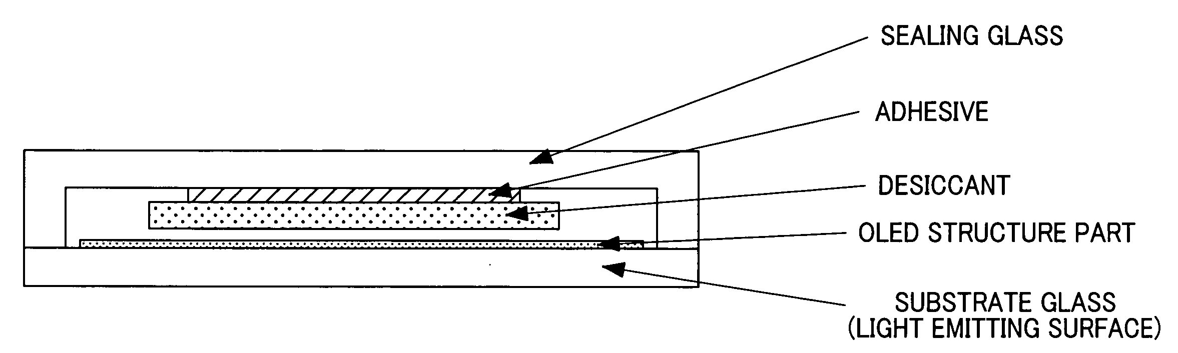
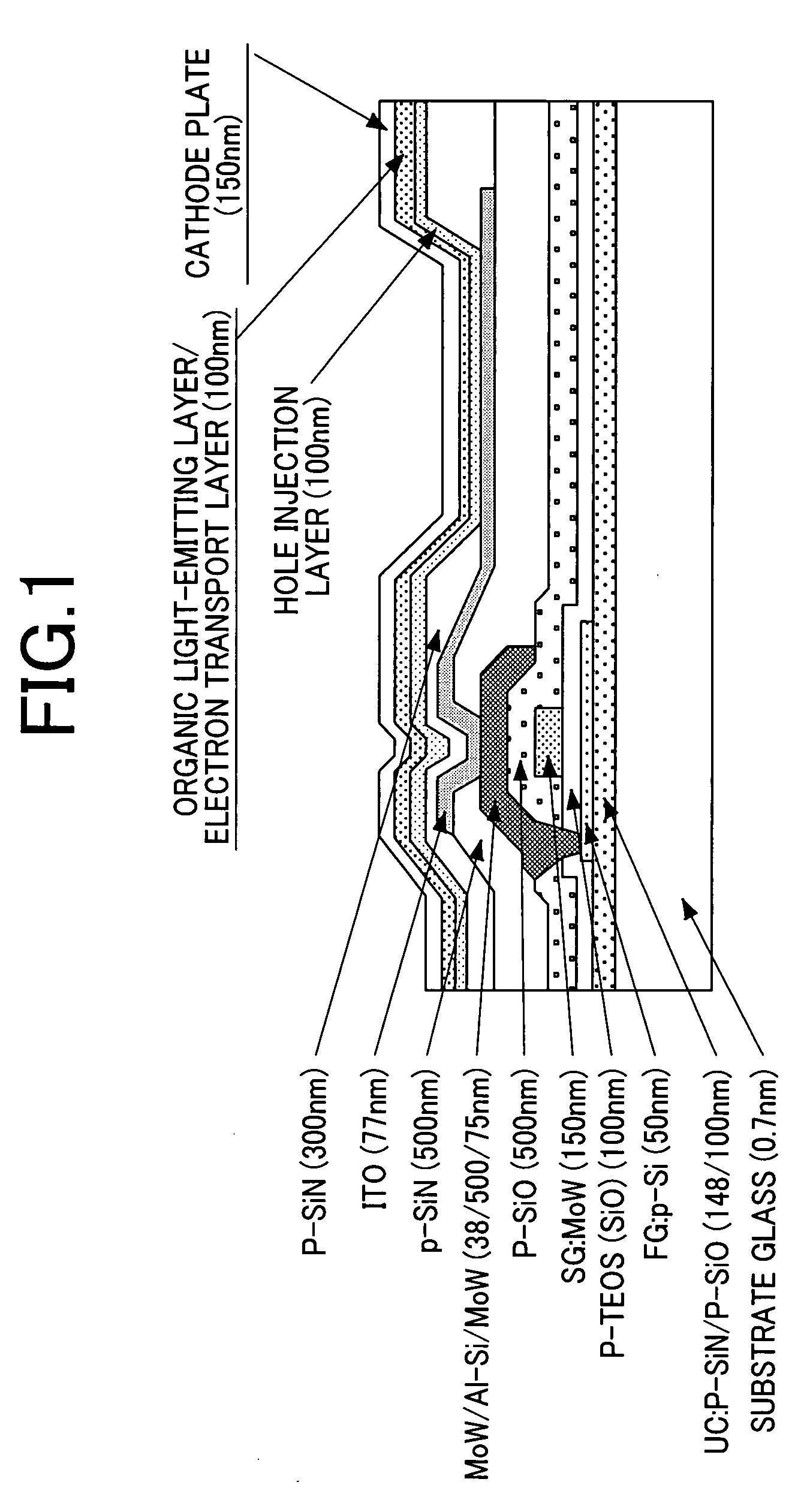
[0038]FIG. 1 shows a sectional structure of a general OLED. Since the OLED shown in FIG. 1 has a structure conventionally know, a detailed description of it is omitted. In FIG. 1, a light emitting surface is in a lower side, and an organic light-emitting layer and a cathode metal are formed via an optically transparent multilayer film about 1 μm from a substrate glass. This structure is called an OLED of a bottom emission method. An OLED of this structure generally has a desiccant and an empty wall in the reverse side of a light emitting part, and is sealed by a sealing glass (or metal such as a sealing can) from external atmospheres.

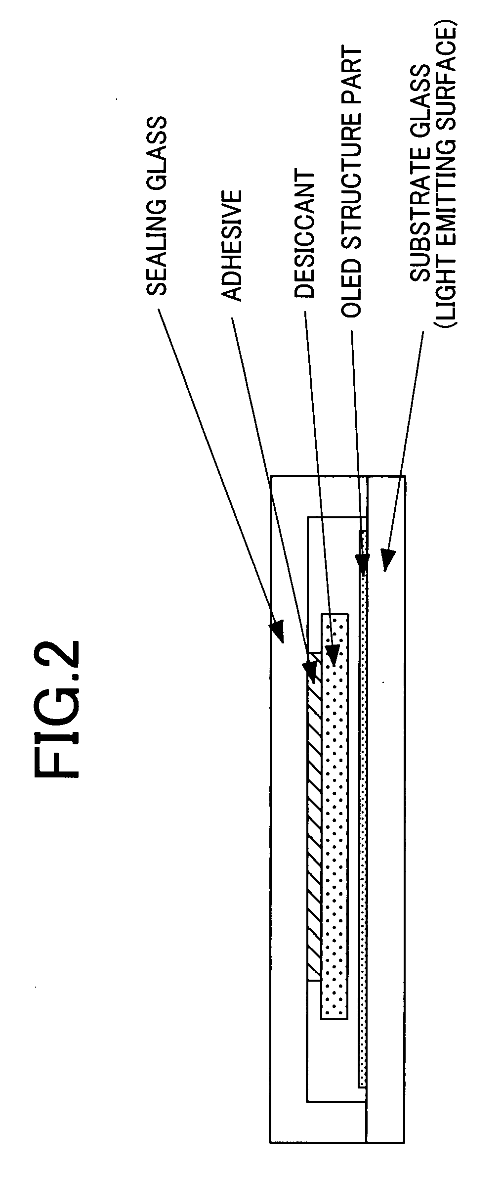
[0039]FIG. 2 shows a sectional structure of the OLED sealed by a sealing glass substrate. In the OLED sectional structure shown in FIG. 2, air tightness is maintained by the empty wall (generally space filled with nitrogen), the desiccant, and the sealing glass to extract heat generated in a structure part of the OLED from the back surface of the light ...


PUM


Abstract

The strength of the whole OLED is increased by proposing a new method of fixing OLED panels. To address the problem, an OLED element is formed on a substrate, and a sealing substrate of a structure by which the substrate is sealed is fixed to a lower metallic frame via an elastic sheet. Silicon resin is preferably used as the sheet, and use of a sheet having a heat diffusion function based on radiation is more desirable.

Description

CLAIM OF PRIORITY[0001]The present application claims priority from Japanese Application JP 2006-051333 filed on Feb. 27, 2006, the content of which is hereby incorporated by reference into this application.BACKGROUND OF THE INVENTION[0002]1. Field of the Invention[0003]The present invention relates to the housing structure of an organic EL display device.[0004]2. Description of the Related Art[0005]As one of display devices, an organic EL display device (hereinafter referred to as OLED) has the following characteristics:[0006]1. A display element constituting the OLED is a self light emitting element that does not require backlight.[0007]2. Wide viewing angle and high visibility[0008]3. The high response speed enables high-quality display without difference between moving images and static images.[0009]4. Direct-current, low-voltage driving is enabled.[0010]Therefore, the OLED is expected to contribute to applications for mobile / portable equipments having severe power requirements,...

Claims


Application Information

Patent Timeline
Patent Type & Authority Applications(United States)
IPC IPC(8): H01J1/62H01J63/04
CPCH01L51/529H01L51/5237H10K50/84H10K50/87
Inventor MATSUDATE, NORIHARUTOYODA, HIRONORI
Owner HITACHI DISPLAYS
Why Eureka
Try Eureka