

Smart RFID reader antennas
a technology of rfid reader and antenna, which is applied in the field of radio frequency identification (rfid) systems, can solve the problems of compact footprint of the packaged rfid interrogation device, and achieve the effect of easy and quick installation or reconfiguration of the reader network
- Summary
- Abstract
- Description
- Claims
- Application Information
AI Technical Summary
Benefits of technology
Problems solved by technology
Method used
Image

Examples
example rfid reader antenna embodiments
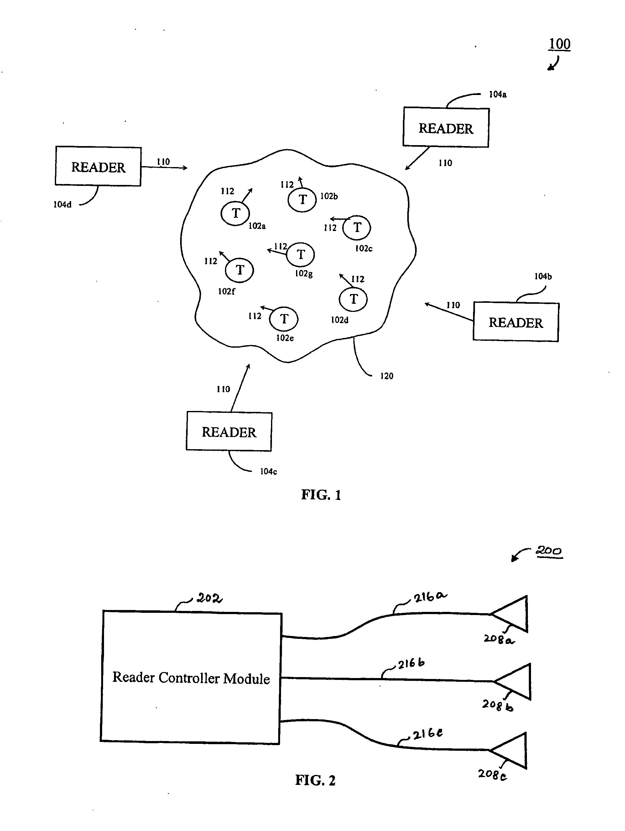
[0036] It is useful to begin with the description of an example environment, where the present invention may be implemented. FIG. 1 describes an environment 100, which includes a population 120 of RFID tags 102a-g, and RFID readers 104a-d. Readers 104a-d may operate independently, or may be connected together to form a reader network. Although not shown explicitly in FIG. 1, each of readers 104a-d is coupled to one or more antennas. When a reader 104 transmits an interrogation signal 110 through its corresponding antenna, one or more transponders or tags 102 respond by sending a signal 112 back to the reader. Signal 112 contains tag identification data, that can be decoded by the interrogating reader 104 in order to retrieve relevant information about a tag 102, such as its price, location etc. Signal 112 may contain information about the operational “state” of a tag 102, which help the reader 104 determine the optimum tag interrogation interval, in case multiple readers are configu...
example rfid reader
Antenna Device Embodiments
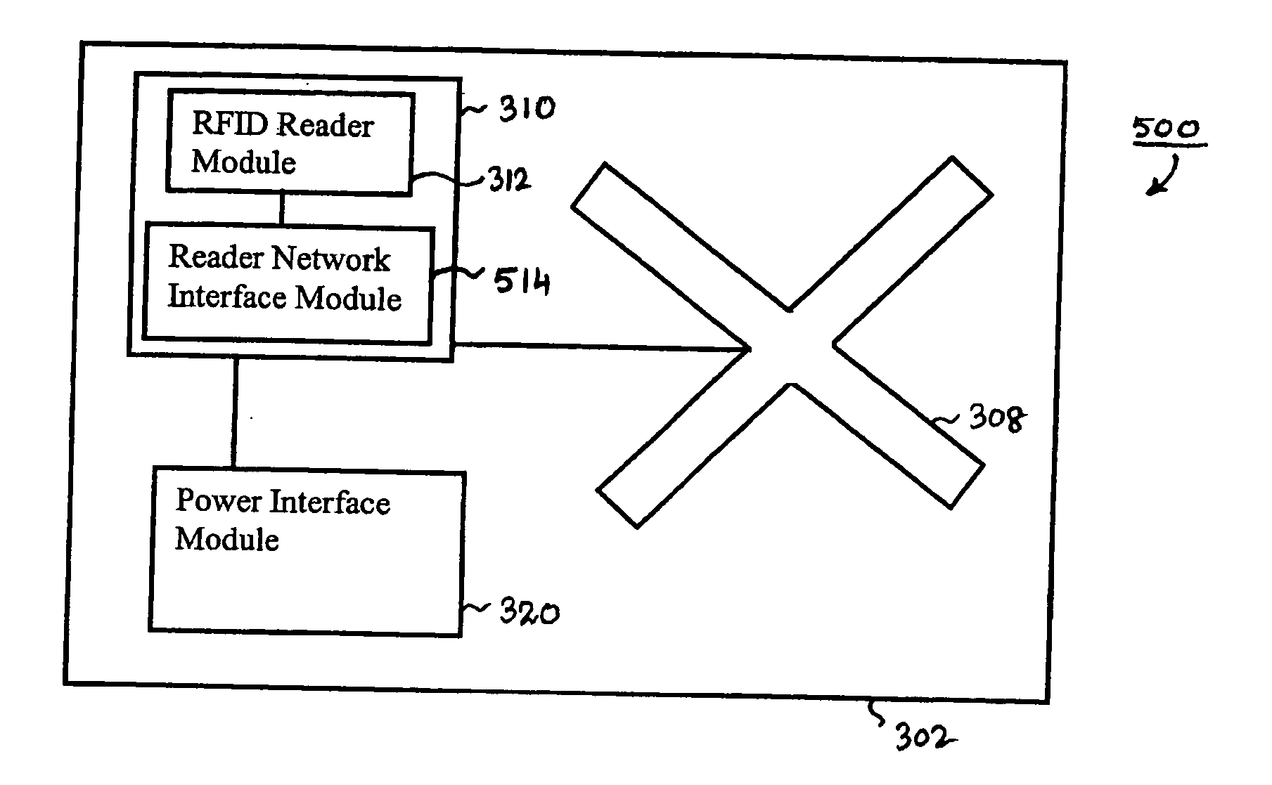
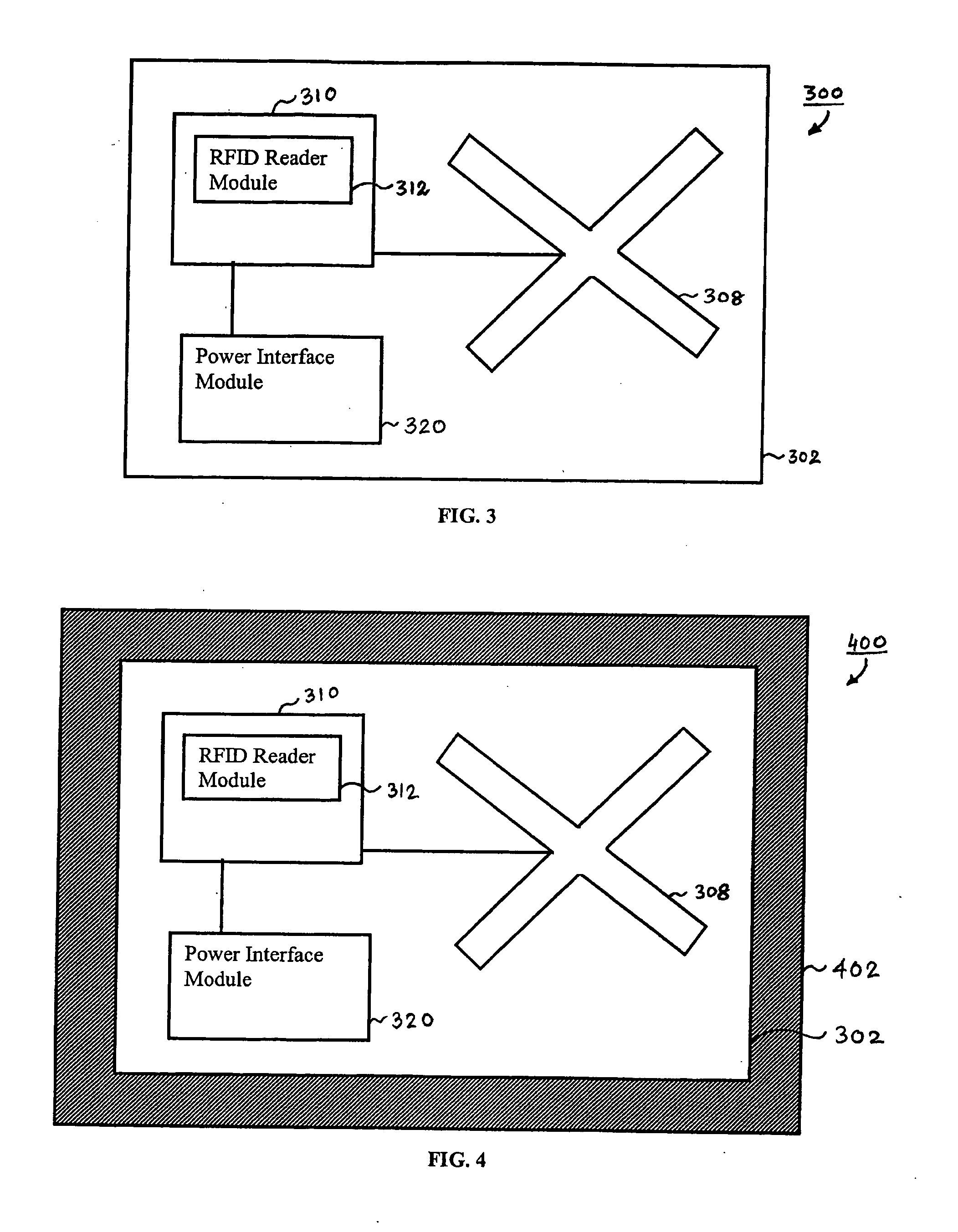
[0040]FIG. 3 shows an example embodiment of a RFID interrogation device 300, according to the present invention. Device 300 has a substrate 302 which supports various functional components. Substrate 302 supports / mounts antenna 308 for communicating with RFID tags located outside of device 300, within a range of antenna 308. In an embodiment, there may be more than one antenna 308 on substrate 302, and the one or more antennas 308 can have any antenna configuration / layout. For example, the different antennas 308 may operate at the same or different interrogation frequency bands and / or communication protocols. Antenna 308 may be formed or printed on substrate 302 in any manner, including by using conductive ink, much in the same way that antennas are printed on RFID tags.
[0041] Substrate 302 also mounts an integrated circuit (IC) chip 310, which contains the functionality of a RFID reader 312. Although a single IC chip 310 is shown for illustrative purposes...
example network embodiments
[0066] Readers, including the smart reader antennas of the present invention, may be networked in various ways to improve coverage of tagged items in the environment. For example, FIG. 14 shows a networked system 1400, according to an example embodiment. System 1400 includes an RFID switch 1402 coupled to readers 1404a-c. For example, readers 1404a-c may be one or more of the readers described elsewhere herein. Readers 1404a-c communicate with one or more tags, such as tag 1406. Tag 1406 may be coupled to an item (e.g., a product), not shown in FIG. 14.
[0067] In embodiments, functions related to RFID communications with tags are split between switch 1402 and readers 1404. For example, in embodiments, switch 1402 is a device that includes one or more functions, including one or more of handling protocol-level functions, sending digitally encoded tag interrogation commands / instructions (e.g., optionally including parameters) to readers 1404, receiving digitally encoded tag responses ...
PUM
 Abstract
Description
Claims
Application Information