Antenna and RFID tag

a technology of rfid tags and antennas, applied in the field of antennas, can solve the problems of difficult to sufficiently increase a bandwidth, the size the complexity of the manufacturing of the rfid tag, so as to increase the frequency bandwidth, increase the bandwidth, and the effect of large bandwidth

Active Publication Date: 2007-08-30
ORMON CORP
View PDF4 Cites 155 Cited by
  • Summary
  • Abstract
  • Description
  • Claims
  • Application Information

AI Technical Summary

Benefits of technology

[0007]According to this configuration, it is possible to increase the bandwidth by the radiating parts, and to adjust the length of the path by the meandering parts, thereby improving the radiation efficiency in a desired wavelength range. In addition, it is possible to suppress the electrostatic coupling occurring between the ends of the radiating parts facing the meandering parts and the portions of the radiating parts facing the sides closest to the radiating parts among the plurality of sides of the meandering parts. Therefore, the deterioration of the radiation efficiency can be suppressed in the desired wavelength range. As a result, it is possible to provide an antenna having a large bandwidth.
[0022]Various implementations may include one or more the following advantages. For example, it is possible to provide an antenna having a large bandwidth. Therefore, for example, it is possible to increase the frequency bandwidth to which the antenna can correspond. As a result, the antenna can be modified depending on a band where the antenna is used. Further, it is possible to reduce the frequency changing the manufacture of an antenna or an RFID tag depending on a band where the antenna is used, thereby improving the efficiency of manufacturing an antenna or an RFID tag. In addition, because the RFID tag needs to be used so as to correspond to each use, it is possible to improve convenience.

Problems solved by technology

In the distribution industry, the size of the RFID tags is limited by the size of baggage.
However, the RFID tags of the related art, in particular, small RFID tags smaller than a size of 1×4 inches for a UHF band has a problem in that it is difficult to sufficiently increase a bandwidth.
As a result, different RFID tags need to be manufactured in each country, thus manufacturing of the RFID tags becomes too complicated.
In addition, it is difficult to use the same RFID tags in each country or for different purposes, which is inconvenient
Accordingly, the manufacturing of the RFID tags becomes too complicated, as described above.

Method used


Image

  • Antenna and RFID tag
  • Antenna and RFID tag
  • Antenna and RFID tag

Examples


first embodiment

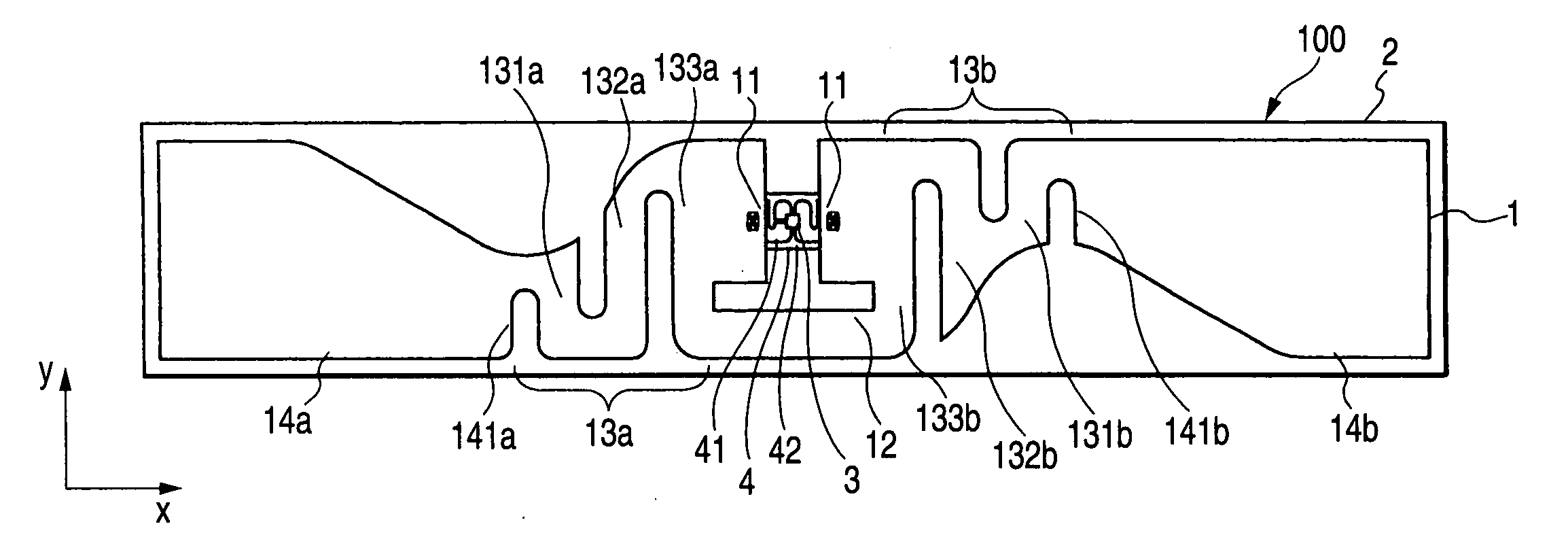
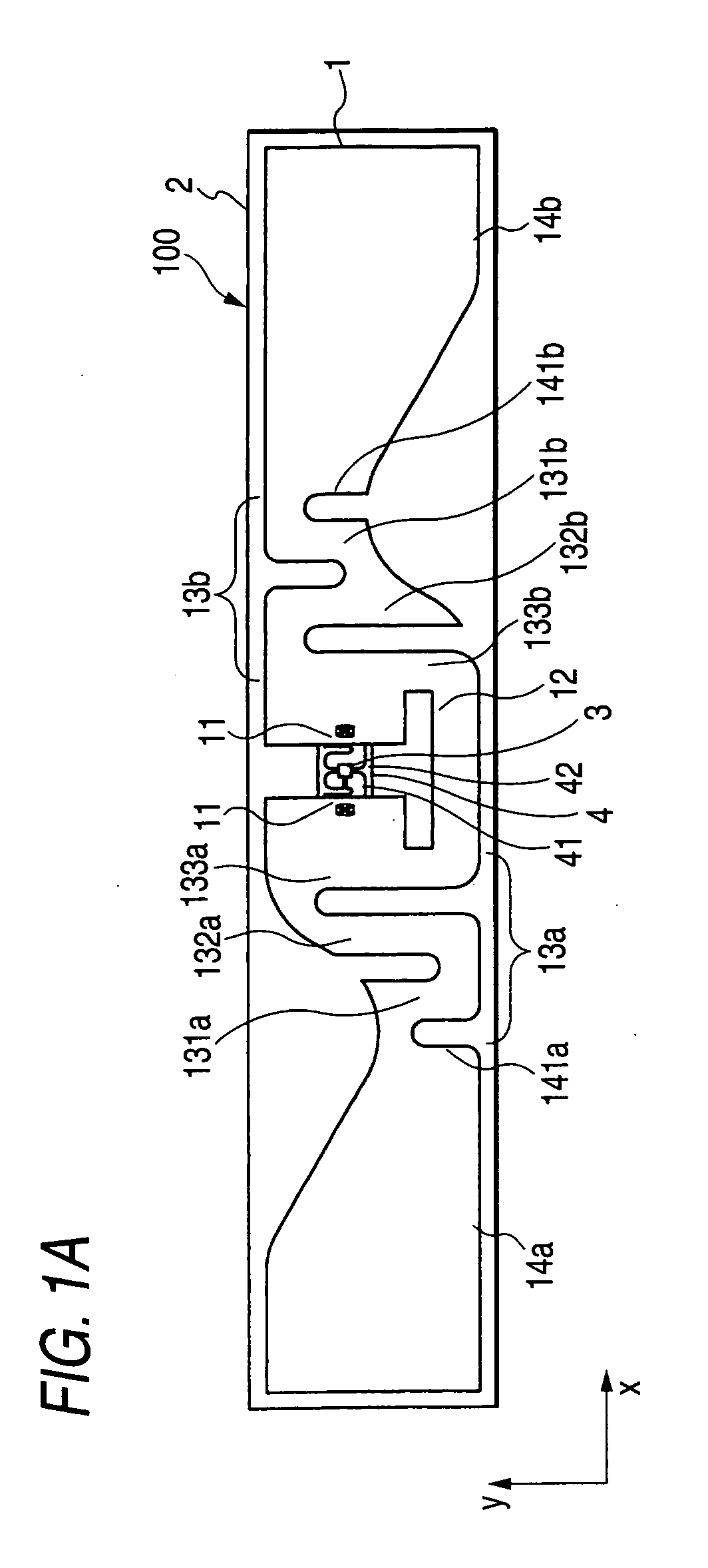
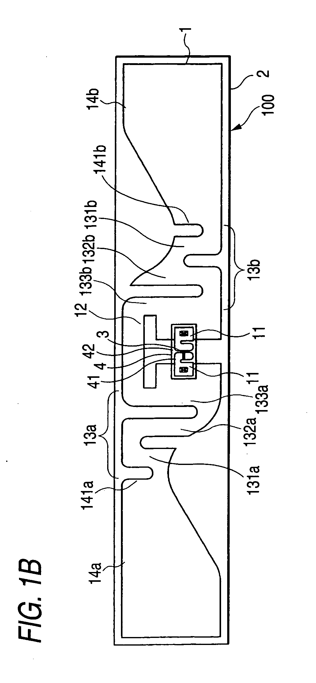
[0039]FIG. 1A is a plan view showing the configuration of an RFID tag according to this embodiment. FIG. 1B is a bottom view showing the configuration of the RFID tag according to this embodiment. FIG. 1C is a front view showing the configuration of the RFID tag according to this embodiment. FIG. 1D is a rear view showing the configuration of the RFID tag according to this embodiment. FIG. 1E is a right side view showing the configuration of the RFID tag according to this embodiment. FIG. 1F is an enlarged view of a portion where a meandering part 13a and a radiating part 14a are connected in the RFID tag according to this embodiment. FIG. 1G is an enlarged view of the vicinity of a portion where a meandering part 13b and a radiating part 14b are connected in the RFID tag according to this embodiment. Further, since a left side view and a right side view are symmetrical, the left side view will be omitted. In the drawings, the RFID tag 100 includes an antenna 1, a dielectric substra...

second embodiment

[0067]An RFID tag according to this embodiment is formed so that the lengths of the sides forming the meandering parts in the direction orthogonal to the longitudinal direction are constant, and the ends of the radiating parts facing the meandering parts are narrower than the widest portions of the radiating parts in the RFID tag 100 according to the first embodiment.

[0068]FIG. 6 is a view showing the configuration of an antenna of the RFID tag according to this embodiment. In FIG. 6, the antenna 20 includes power feeding parts 21, a matching circuit 22, meandering parts 23a and 23b, and radiating parts 14a and 14b. The power feeding parts 21 and the matching circuit 22 have the same configuration as the power feeding parts 11 and the matching circuit 12 of the antenna 1 according to the first embodiment. Accordingly, the description thereof will be omitted. In addition, the meandering parts 23a and 23b have the same configuration as the meandering part 13a and 13b according to the ...

third embodiment

[0071]An RFID tag according to this embodiment is formed so that the lengths of the sides forming the meandering parts in the direction orthogonal to the longitudinal direction are constant, and the ends of the radiating parts facing the meandering parts decrease as coming close to the meandering parts in the RFID tag according to the first embodiment.

[0072]FIG. 7 is a view showing the configuration of an antenna of the RFID tag according to this embodiment. In FIG. 7, the antenna 30 includes power feeding parts 31, a matching circuit 32, meandering parts 33a and 33b, and radiating parts 34a and 34b. The power feeding parts 31 and the matching circuit 32 have the same configuration as the power feeding parts 11 and the matching circuit 12 of the antenna 1 according to the first embodiment. Accordingly, the description thereof will be omitted. In addition, the meandering parts 33a and 33b have the same configuration as the meandering parts 13a and 13b according to the first embodimen...


PUM


Abstract

An antenna for an RFID tag includes each power feeding parts 11 that is formed of a conductor, meandering parts 13a and 13b that are formed of conductors shaped as a pair of meandering lines, connected to the power feeding parts 11, and extend from the power feeding parts 11 toward both ends of the power feeding parts 11, respectively, a pair of radiating parts 14a and 14b that are formed of conductors and connected to outer ends of the pair of meandering parts 13a and 13b, respectively. The meandering parts 13a and 13b include a plurality of sides arranged in a longitudinal direction where the meandering parts 13a and 13b extend. Further, the lengths of portions, where the ends of the radiating parts 14a and 14b facing the meandering parts 13a and 13b face the sides closest to the radiating parts 14a and 14b among the plurality of sides of the meandering parts 13a and 13b in a direction orthogonal to the longitudinal direction, are smaller than the widths of the widest portions of the radiating parts.

Description

TECHNICAL FIELD[0001]The present disclosure relates to an antenna used in an RFID (Radio Frequency Identification) tag.RELATED ART[0002]In the related art, various RFID tags (for example, see Patent Document 1: U.S. Pat. No. 6,281,794 (page 1 and FIG. 1)) have been proposed, and it has been conceived that an RFID is used for various purposes. For example, RFID tags are used as labels for baggage of the distribution industry in America where systems using RFID tags used in the UHF band are used. In the distribution industry, the size of the RFID tags is limited by the size of baggage. In particular, since RFID tags having a size of 1×4 inches (about 25 mm×100 mm) are widely used as labels, and RFID tags smaller than the 1×4 inches are widely used as the RFID tags used in the UHF band.[0003]However, the RFID tags of the related art, in particular, small RFID tags smaller than a size of 1×4 inches for a UHF band has a problem in that it is difficult to sufficiently increase a bandwidth...

Claims


Application Information

Patent Timeline
Patent Type & Authority Applications(United States)
IPC IPC(8): H01Q9/28H01Q1/38
CPCG06K19/07786H01Q1/2208H01Q9/285H01Q9/24H01Q1/38
Inventor HAYAMA, KOSUKESAITO, KEISUKE
Owner ORMON CORP
Why Eureka
Try Eureka