Cell voltage detection device and cell system using the same

a cell voltage detection and cell technology, applied in cell components, instruments, electrochemical generators, etc., can solve problems such as false detection of detection data of a/d converter elements, and achieve the effect of preventing false detection of cell voltage detection data

Inactive Publication Date: 2007-08-30
HITACHI LTD
View PDF1 Cites 45 Cited by
  • Summary
  • Abstract
  • Description
  • Claims
  • Application Information

AI Technical Summary

Benefits of technology

[0011]According to the present invention, it is possible to provide a cell voltage detection device capable of preventing the false detection of cell voltage detection data.

Problems solved by technology

Because of this feature, in the case where the operating power source of an A / D converter element and the reference voltage for A / D conversion are supplied from the voltage of the fuel cell, a false detection of detection data of the A / D converter element may occur when a plurality of cell voltages decrease at the same time.

Method used


Image

  • Cell voltage detection device and cell system using the same
  • Cell voltage detection device and cell system using the same
  • Cell voltage detection device and cell system using the same

Examples


embodiment 1

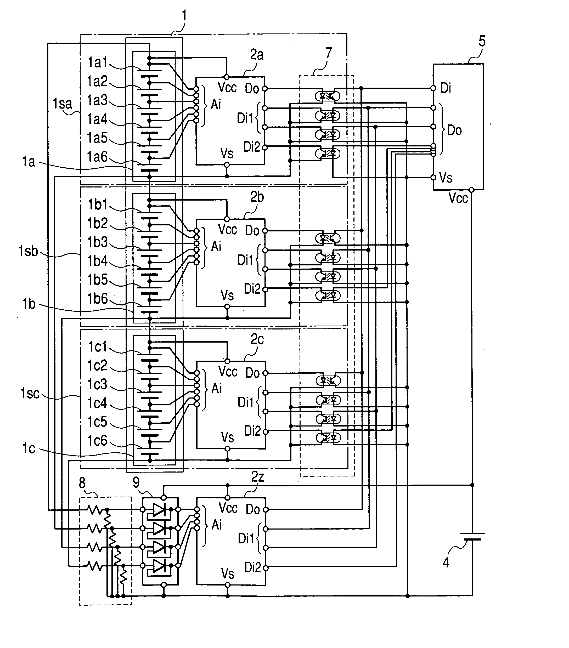
[0023]The embodiment will be described with reference to FIG. 1. Fuel cells 1a1, 1a2, 1a3, 1a4, 1a5, 1a6 shown in FIG. 1 are connected in series so that the fuel cell of the smaller numeral has a higher potential, forming a fuel cell block 1a. Similarly, fuel cells 1b1 to 1b6 and 1c1 to 1c6 respectively form fuel cell blocks 1b, 1c. Further, fuel cell blocks 1a, 1b, 1c are connected in series so that the fuel cell block of the smaller numeral has a higher potential, forming a fuel cell stack 1. Here, the configuration where the fuel cells are laminated via a separator may be considered as a series connection of the fuel cells or fuel cell blocks. In FIG. 1, the six fuel cells within the fuel cell block are connected in series and the three fuel cell blocks within the fuel cell stack are connected in series. However, it may be configured that other plural number of fuel cells and blocks are connected in series.

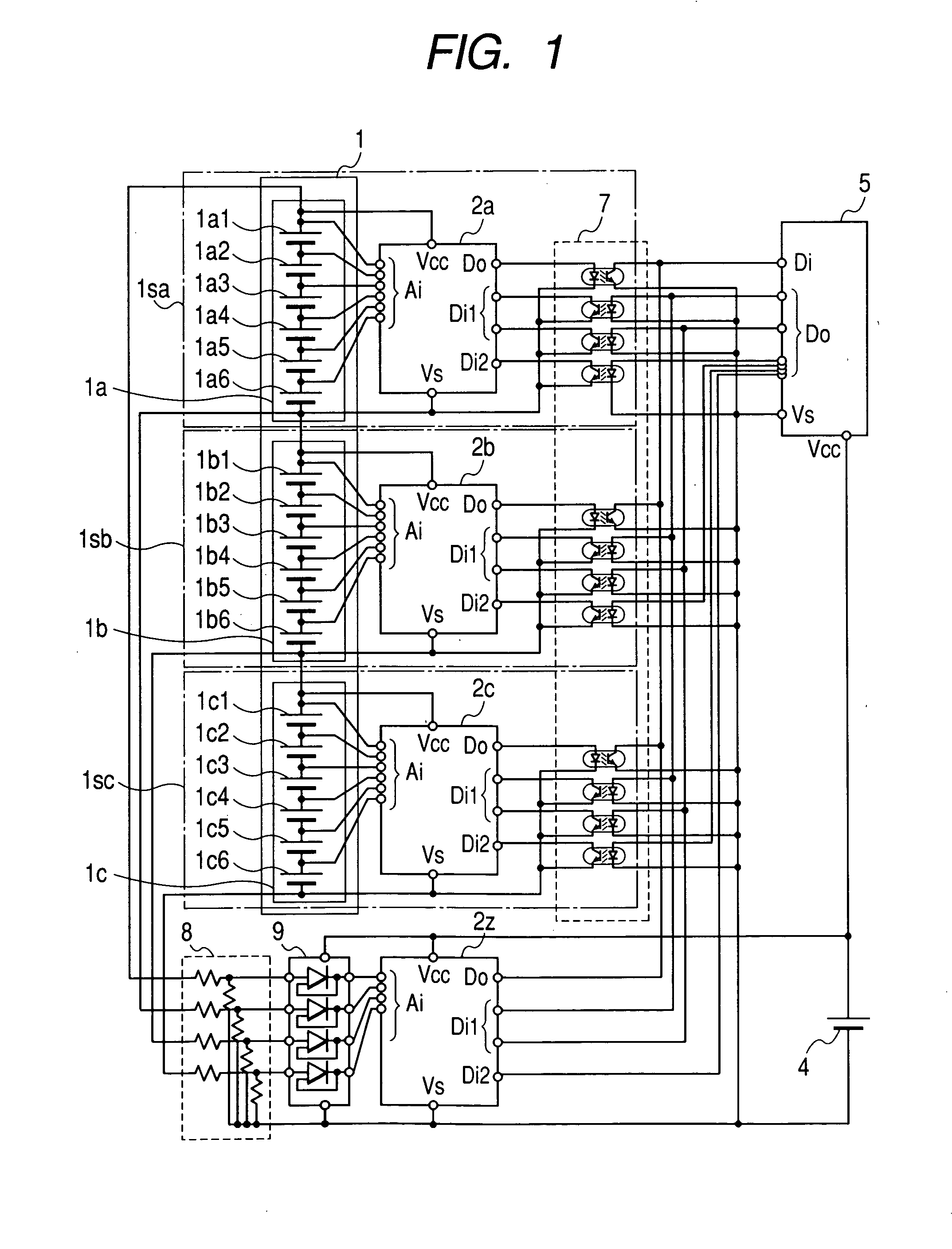
[0024]Connected to the fuel cell blocks 1a, 1b, 1c are A / D converter eleme...

embodiment 2

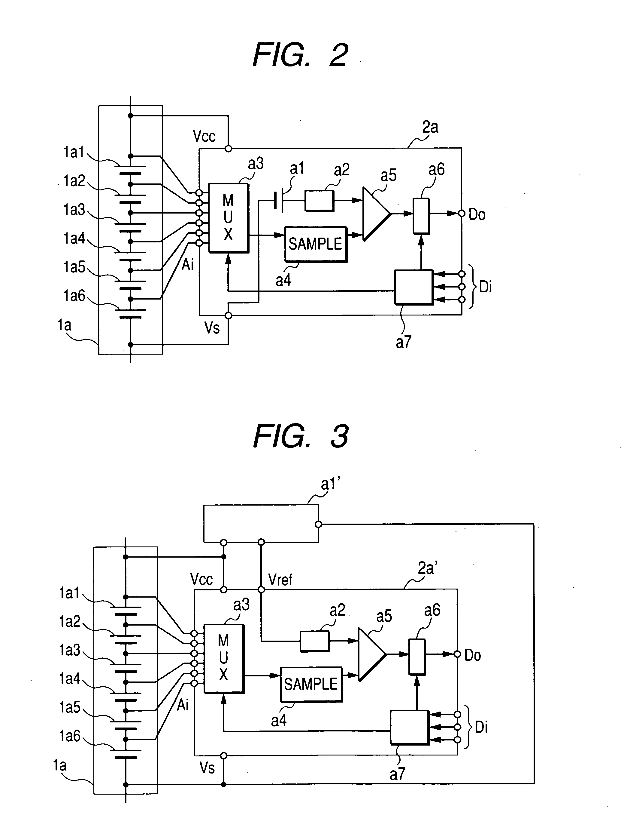
[0037]The embodiment will be described with reference to FIG. 6. The same reference numerals are given to the components having the same functions as in Embodiment 1, and the detailed description thereof will be omitted. In the embodiment, as shown in FIG. 6, the maximum potential of each fuel cell block is connected to the reference voltage terminal Vref of the A / D converter element provided in the each fuel cell block. With such a configuration, the digital value of the cell voltage obtained from the A / D converter element 2a outputs a relative value of the voltage of the analog input terminal Ai relative to the both end voltage of the fuel cell block 1a to be measured.

[0038]Similarly to Embodiment 1, as the absolute value of the both end voltage of the fuel cell block 1a is measured by the A / D converter element 2z, for example, the voltage of the fuel cell 1a1 can be detected by multiplying the absolute value detected in the A / D converter element 2z, by the relative value of the f...

embodiment 3

[0040]The embodiment will be described with reference to FIG. 7. In an enclosure M11 of a fuel cell module shown in FIG. 7, a fuel cell stack M1 formed by laminating a plurality of fuel cells, a booster converter M2, and a cell state monitoring board M3 are housed. The outer surface of the enclosure M11 is provided with a terminal block M13 and a communication connector M12. A light-emitting diode (LED) or liquid crystal panel for displaying the state of the fuel cell module may be mounted to the outer surface of the enclosure M11. Further, connected to the enclosure M11 are: fuel supply means M8i for circulating the hydrogen-rich gas to be the fuel gas of the fuel cell stack M1; exhaust gas discharge means M8o for discharging the exhaust gas after hydrogen, which is a part of the hydrogen-rich gas supplied from the fuel supply means M8i, is consumed in the fuel cell stack M1; and heat carrier supply means M9i and heat carrier discharge means M9o for circulating the heat carrier for...


PUM

PropertyMeasurementUnit
electromotive forceaaaaaaaaaa
voltageaaaaaaaaaa
voltageaaaaaaaaaa

Abstract

A fuel cell detection device according to the present invention includes: a cell block formed with a plurality of cells serially connected to each other; a voltage detection element for detecting voltages of the cells within the cell block; and another voltage detection element for detecting a voltage of the operating power source of the voltage detection element, where the operating power source of the voltage detection element is supplied from a voltage of the inside or both ends of the cell block, and the operating power source of another voltage detection element is supplied from a voltage of the outside of the cell block, the operating power source of another voltage detection element being less variable than the operating power source of the voltage detection element.

Description

CLAIM OF PRIORITY[0001]The present application claims priority from Japanese application No. 2006-051464, filed on Feb. 28, 2006, the content of which is hereby incorporated by reference into this application.BACKGROUND OF THE INVENTION[0002]1. Field of The Invention[0003]The present invention relates to a cell voltage detection device for detecting voltages of fuel cells of a fuel battery stack formed with a plurality of fuel cells serially connected to each other, and to the cell system using a cell voltage detection device.[0004]2. Description of the Prior Art[0005]Recently, fuel cells have been considered as an energy source with reduced environmental load. For example, the use of a polymer electrolyte fuel cell (PEFC) has been studied as an energy source of a cogeneration system using its heat and electric power or as a power source of an electric vehicle.[0006]The fuel cell is a device that obtains electromotive force by electrochemically reacting the fuel gas containing hydro...

Claims


Application Information

Patent Timeline
Patent Type & Authority Applications(United States)
IPC IPC(8): H01M8/04G01R31/02
CPCG01R31/3658H01M8/04365H01M8/04753Y02E60/50H01M8/04947H01M8/24H01M8/0494G01R31/396
Inventor TAKEDA, KENJIKAWAZOE, HIRONARIFUTAMI, MOTOOKOMACHIYA, MASAHIRO
Owner HITACHI LTD
Why Eureka
Try Eureka