
Solid Electrolyte Fuel Cell

a fuel cell and solid electrolyte technology, applied in the field of solid electrolyte fuel cells, can solve the problems of water content unduly reduced, difficulty in stable supply of oxidizing agent or maintaining conductivity, and difficulty in cell having a conventional configuration, so as to achieve the effect of preventing crossover or reducing water content in the cathode, reducing the use efficiency and reducing the water conten

Inactive Publication Date: 2007-08-30
NEC CORP
View PDF5 Cites 5 Cited by
  • Summary
  • Abstract
  • Description
  • Claims
  • Application Information

AI Technical Summary

Benefits of technology

The present invention provides a technique for maintaining a low water content in the cathode of a fuel cell and stable supplying of an oxidizing agent to the cell. This is achieved by using an evaporation inhibiting layer that prevents excessive drying of the cathode and allows for stable supplying of the oxidizing agent. The evaporation inhibiting layer has venting pores that allow for supplying the oxidizing agent and maintaining a low water content. The water content in the cathode can be increased due to water generated in the cathode, but the evaporation inhibiting layer retains water and allows for stable supplying of the oxidizing agent. This technique improves the output properties of the fuel cell.

Problems solved by technology

There is, however, a new problem that water content may be unduly reduced, so that a cathode may be dried not as expected in a conventional DMFC.
When a water-absorbing layer which absorbs water generated in a cathode is formed for preventing the above problem, the state of inner small pores is changed as a water content in the water-absorbing layer increases, leading to difficulty in stable supplying of an oxidizing agent or in maintaining conductivity.
It has been thus difficult in a cell having a conventional configuration to maintain a suitable low water content of a cathode or to maintain constant water-retentive layer properties regardless of a water content.

Method used


Image

  • Solid Electrolyte Fuel Cell
  • Solid Electrolyte Fuel Cell
  • Solid Electrolyte Fuel Cell

Examples


embodiment 2

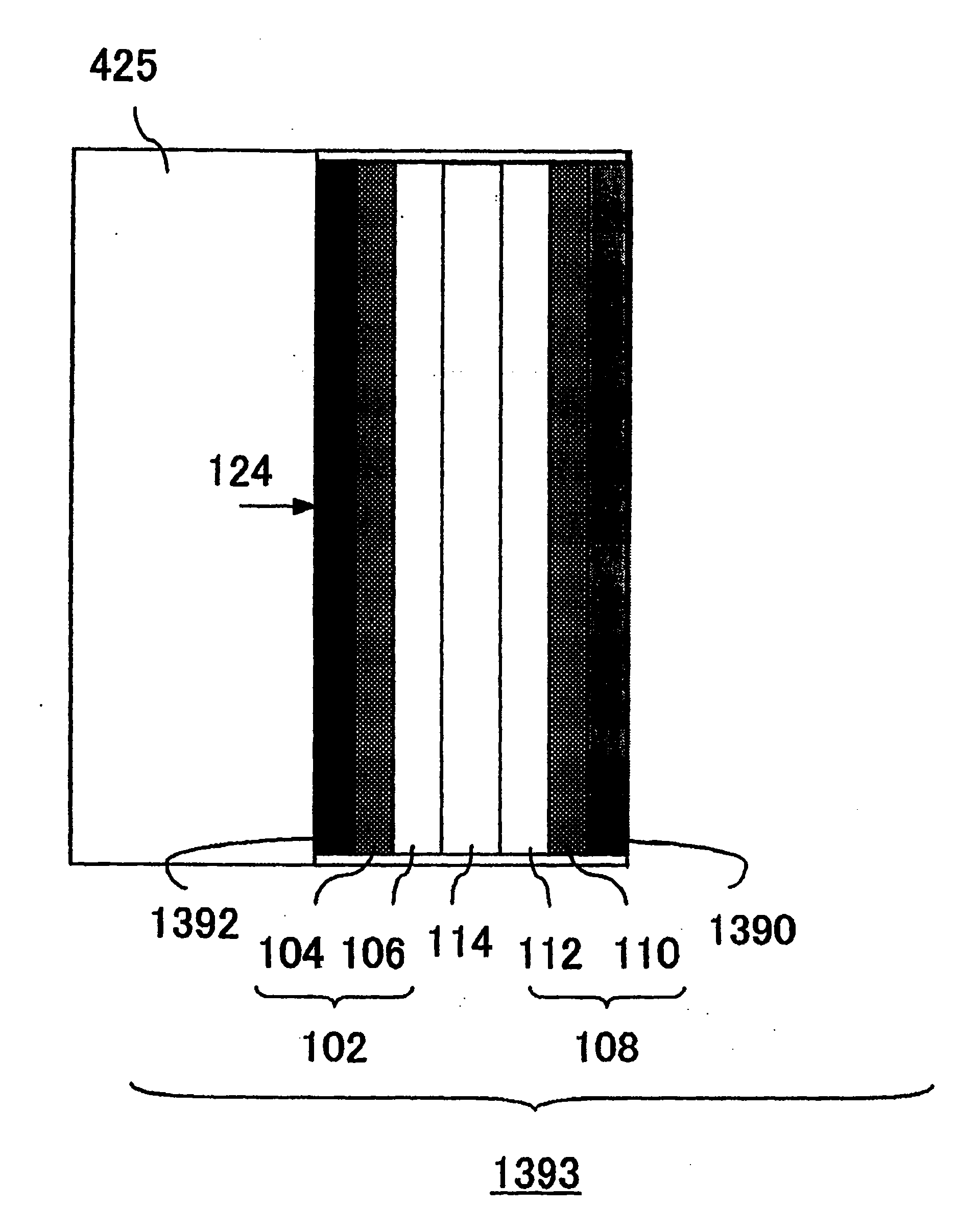
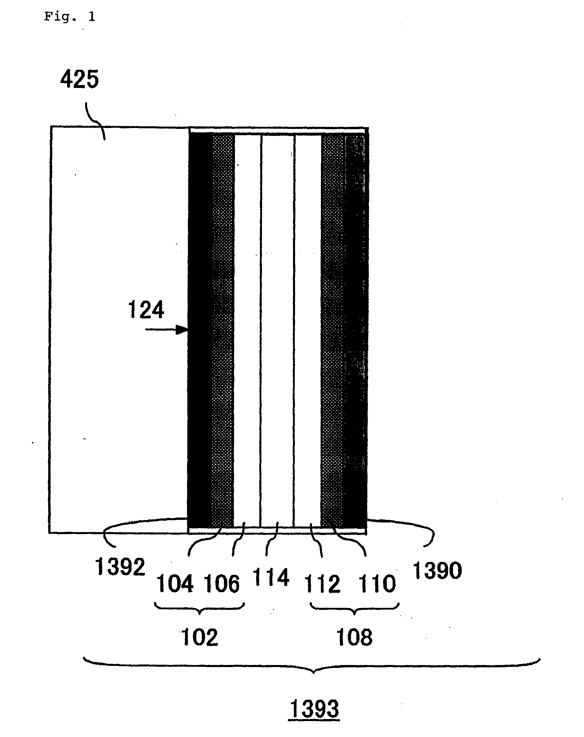
[0080] Herein, a single cell structure has a configuration basically as in the single cell structure 1393 of FIG. 1, except that two members are used as an evaporation inhibiting layer 1390.

[0081] Specifically, next to a cathode is placed a fibrous cellulose sheet as an evaporation inhibiting layer 1390, on which is placed a punching plate having a number of venting pores. The punching plate protects the outer surface of the evaporation inhibiting layer 1390 and more effectively prevent drying of the inside of the evaporation inhibiting layer 1390 from its surface while supplying an oxidizing agent 126 into the single cell structure 1393. Permeation of the oxidizing agent 126 and water can be easily controlled by adjusting a numerical aperture of the punching plate.

[0082] The punching plate is preferably a metal plate such as an aluminum plate and a stainless plate having an opening. Alternatively, the punching plate may be a plastic plate such as a PTFE plate having venting pores...

embodiment 3

[0083] In Embodiment 3, a fuel-absorbing member is placed in contact with the outer surface of a limited permeation layer 1392 in a single cell structure 1393 (FIG. 1). In this embodiment, an evaporation inhibiting layer 1390 consists of two members, fibrous cellulose and a punching plate.

[0084]FIG. 3 is a cross-sectional view schematically showing a configuration of a single cell structure as a constitutional unit in a fuel cell according to this embodiment. A single cell structure 1394 shown in FIG. 3 has a configuration as in the single cell structure 1393 shown in FIG. 1, a container 425 adjacent to a limited permeation layer 1392 has a fuel-absorbing part 1396 which is opposite to the limited permeation layer 1392 and is in contact with its outer surface. In the periphery of the surface of the limited permeation layer 1392, there is formed a non-contact part 1395 which is not in contact with the fuel-absorbing part 1396.

[0085] The fuel-absorbing part 1396 may be made of a mat...

example 1

[0097] Cell B: a PTFE sheet (limited permeation layer) was adhered to the outer surface of the anode and a fibrous cellulose sheet (evaporation inhibiting layer) was adhered to the outside of the cathode (the surface opposite to the surface contacting with Nafion 117).


PUM

PropertyMeasurementUnit
temperatureaaaaaaaaaa
diameteraaaaaaaaaa
thicknessaaaaaaaaaa

Abstract

Output properties of a fuel cell can be improved by using a single cell structure 1387 having an anode 102 and an oxidizing agent electrode 108 in both sides of a solid electrolyte membrane 114 and an evaporation inhibiting layer 1388 covering the surface of the cathode 108 which is not in contact with the solid electrolyte membrane 114.

Description

TECHNICAL FIELD [0001] The present invention relates to a solid electrolyte fuel cell. BACKGROUND OF THE INVENTION [0002] A solid electrolyte fuel cell is composed of an anode, a cathode and a solid electrolyte membrane between them. A fuel and an oxidizing agent supplied to the anode and the cathode, respectively, and the solid electrolyte fuel cell is subjected to an electrochemical reaction to generate electric power. Each of the anode and the cathode has a substrate (an anode collector and a cathode collector) and a catalyst layer on the substrate surface. Although hydrogen is commonly used as a fuel, there have been intensely developed methanol-reformed type fuel cells where hydrogen is generated by reforming methanol as a starting material which is inexpensive and easily handled and direct type fuel cells which directly utilize methanol as a fuel (hereinafter, simply referred to as “DMFC”). [0003] In a DMFC, an anodic reaction is represented by the following equation (1): CH3O...

Claims


Application Information

Patent Timeline
Patent Type & Authority Applications(United States)
IPC IPC(8): H01M8/02H01M8/04H01M8/10
CPCH01M8/023H01M8/0245Y02E60/523H01M8/1011H01M8/04186Y02E60/50
Inventor NAKAMURA, SHINSASAKI, HIDEAKISEKINO, SHOJIOBATA, TAKESHIYOSHITAKE, TSUTOMUKUBO, YOSHIMIKOBAYASHI, KENJI
Owner NEC CORP
Learn More