Apparatus and method for sampling and correcting fluids

a fluid and apparatus technology, applied in the field of apparatus and method for sampling and correcting fluids, can solve the problems of non-conformity, inconformity, and insufficient fluidity, and achieve the effect of eliminating “guess work”

Inactive Publication Date: 2007-08-30
COUNTS STEVEN WAYNE
View PDF99 Cites 14 Cited by
  • Summary
  • Abstract
  • Description
  • Claims
  • Application Information

AI Technical Summary

Benefits of technology

[0024]The present invention provides an advantageous computerized comparison of the contaminates and concentrations of key constituents in a sample fluid against desired operating parameters and dispenses a corrective fluid, which, when added to the reservoir from which the sample fluid was drawn, corrects the adverse conditions of that fluid. The invention eliminates “guess work” in maintaining MWF's and closes the implementation gaps noted above. The present invention is useful for the treatment of multiple reservoirs that use MWF's, but one of ordinary skill in the art would readily recognize various other applications for these teachings within the spirit and scope of this disclosure.

Problems solved by technology

This approach invariably causes the fluid to go from too rich to too lean or vice versa.
The resulting duplication of labor requirements for re-testing and re-adjusting chemicals can be costly.
Additionally, a MWF having chemical concentrations not within the proper ranges can result in non-conforming parts, high tool failure rates, excessive chemical costs, and an increase in certain health risks associated with exposure to higher chemical concentrations.
Although these instruments for measuring chemical concentration are readily available, there remains a gap in the industry between the results of the analysis and the corrective action needed and taken.
With a refractometer, for example, the user will obtain a reading, but it will not convert this data into a quantitative concentration of the chemical of interest, nor will the instrument calculate the amount of chemical concentrate and / or water required to return the chemical reservoir to the target or optimum concentration.
As noted above, however, it is not common practice in the metal working industry that these calculations are actually carried out.
Furthermore, improper control of chemical concentration is the single largest contributor to coolant related machining problems.
When concentrations of the active chemicals become too low, tool life is shortened dramatically and rust and corrosion begin to take place on the machine tools and on the manufactured parts.
Surface finish is impaired and microbial and fungus growth begins to flourish.
Similarly, when the metal working fluids become too rich, tool life is again shortened due to impairment of heat dissipation caused by increased fluid viscosity.
Maintenance of machinery becomes a problem because heavy, sticky residue begins to accumulate on machine surfaces and tool holders.
Operators begin complaining of dermatitis or respiratory problems as the chemicals become more concentrated.
Excessive chemical consumption and related costs become significant issues.
Instead, most companies change the fluid in coolant reservoirs when the coolant becomes rancid, producing unpleasant odors, or when solids build up in the reservoirs to the point that pumps become clogged and coolant flow to the machine is impaired.
Problems associated with microbial growth in metal working fluid include degradation of the coolant supply; drop in pH; emulsion instability; potential health risks including skin irritation and dermatitis, among others; generation of foul odors; increased corrosion and staining of the parts produced; and shortened tool life.
When bacteria levels become too high, the bacteria create an acidic byproduct, causing the pH to drop.
When the pH falls to a level in which the MWF becomes mild to moderately acidic, the coolant becomes corrosive to ferrous metals, causing rust and corrosion of the work piece, tool holders and other machine surfaces.
Normally, when the pH becomes too high, it is the result of cross contamination by high alkaline chemicals.
When the pH of a MWF is too high, it attacks non-ferrous metals, causing corrosion, pitting and staining.
Additionally, high pH levels are harsh on human skin tissue, causing irritation, including dermatitis.
High levels of conductivity can create an environment in which electrolysis caused by dissimilar metals is accelerated, causing corrosion, pitting and staining.
It has been found that dramatic reductions in tool life result from excessive tramp oil contamination in metal working fluids.
Additionally, tramp oil is a primary food source for bacteria, causing foul odors, shortened sump life and other bacteria related concerns, as previously described.
Excessive solids in the coolant supply can result in a number of machining problems including clogged coolant lines and pumps; tool holders that fail to release; poor surface finish; inability to maintain critical machining tolerance; and excessive machine and tool wear.

Method used


Image

  • Apparatus and method for sampling and correcting fluids
  • Apparatus and method for sampling and correcting fluids
  • Apparatus and method for sampling and correcting fluids

Examples


Embodiment Construction

[0039]The embodiments of the present invention described below are not intended to be exhaustive or to limit the invention to the precise forms disclosed in the following detailed description. Rather, the embodiments are chosen and described so that others skilled in the art may appreciate and understand the principles and practices of the present invention.

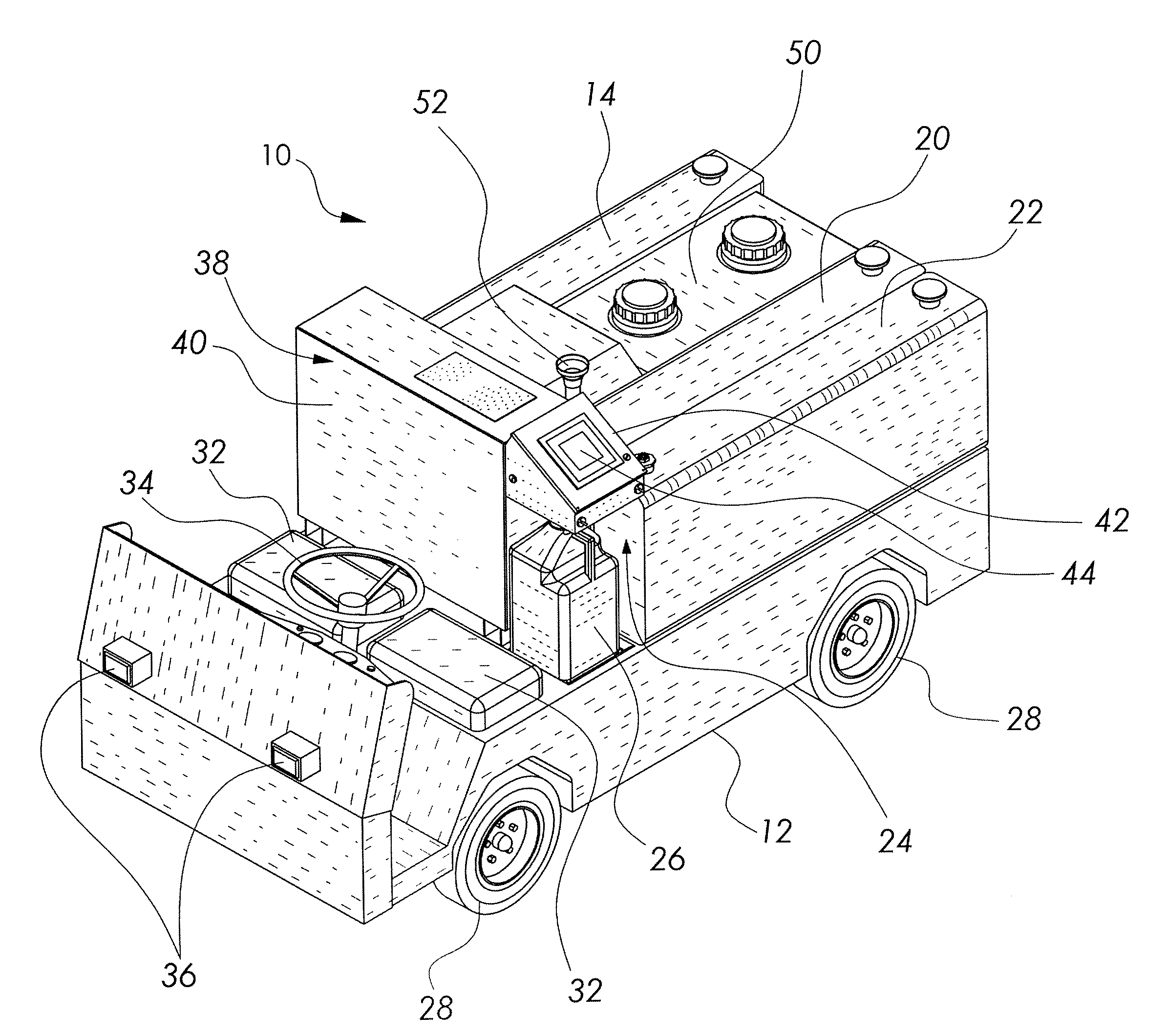
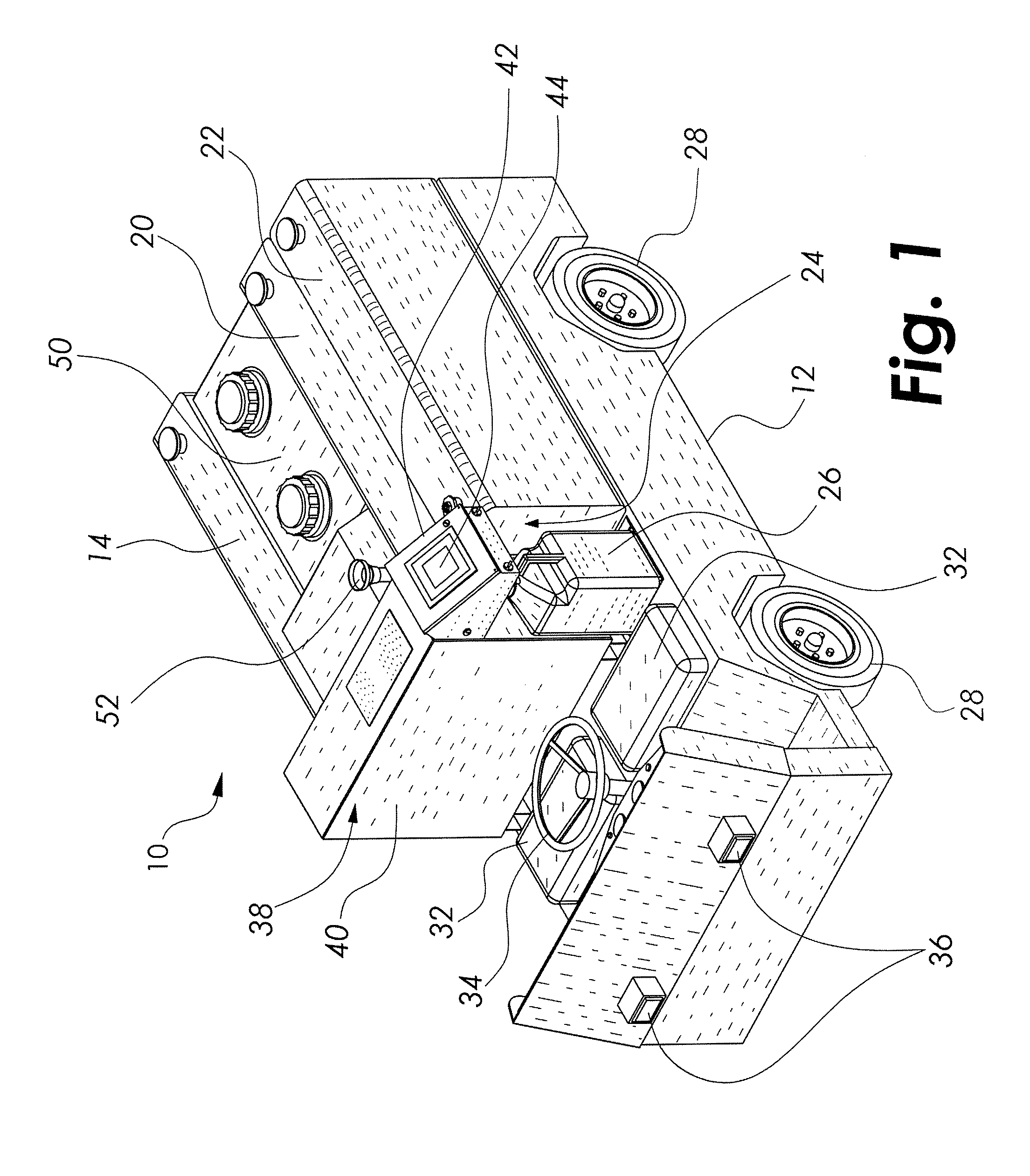
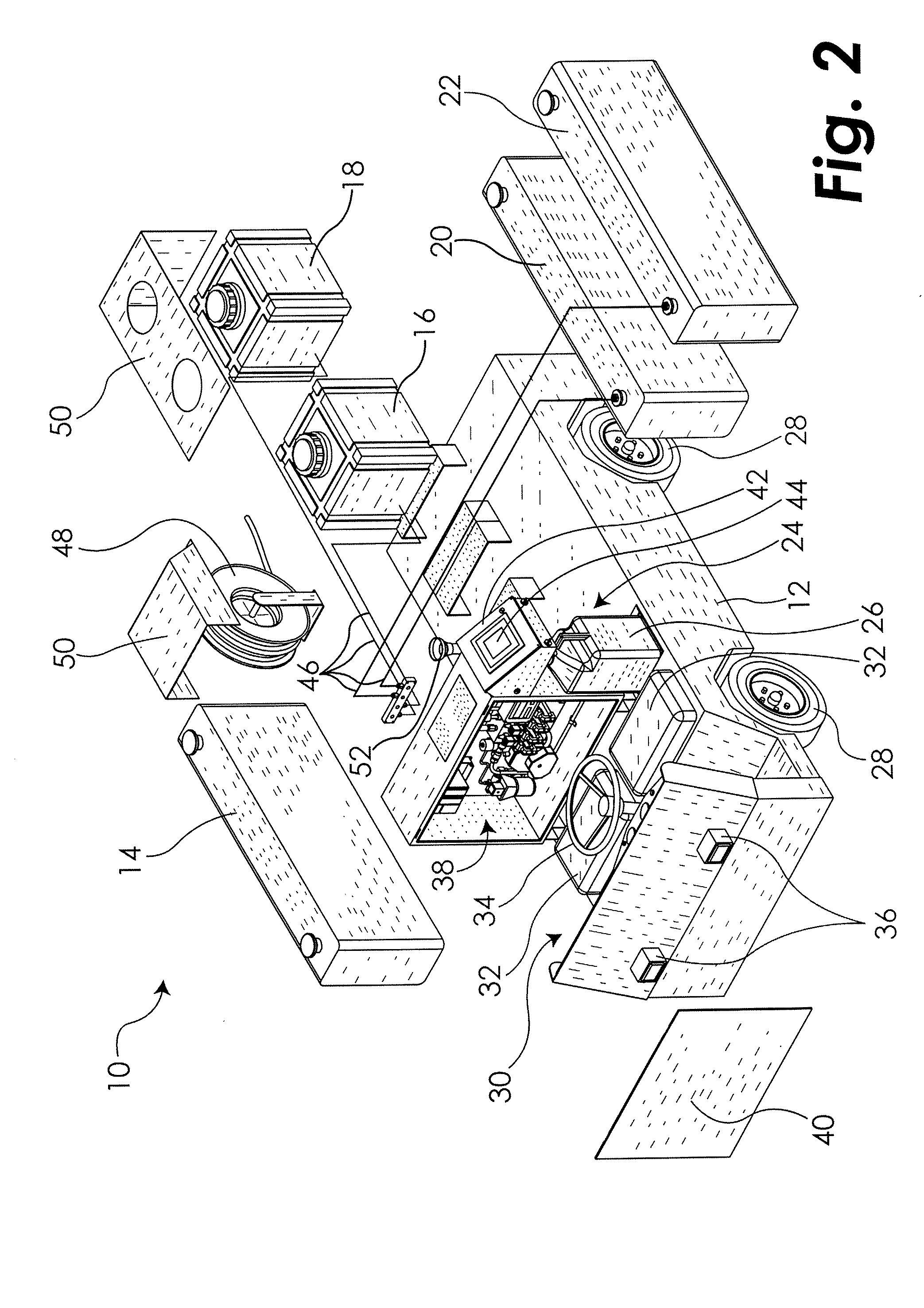
[0040]Turning now to FIGS. 1 and 2, mobile chemical dispensing apparatus or unit 10 includes a base or frame 12 to which is mounted several tanks 14, 16, 18, 20 and 22. A wide variety of tanks are suitable, one such tank being available from Park Plastic, part no. SP0012RT, 12 gal. Unit 10 includes a dispensing station 24 that includes a removable container 26 into which a precise amount of corrective fluid with a desired concentration of active chemical(s) is dispensed, as described in further detail below. Unit 10 is mobile, having wheels 28 and a cab 30 including removable seats 32 and steering wheel 34. Although unit 10 is sh...


PUM

PropertyMeasurementUnit
refractive indexaaaaaaaaaa
volumeaaaaaaaaaa

Abstract

The present invention provides an apparatus and method for sampling a metal working fluid and dispensing a corrective fluid to adjust the fluid in a tank or reservoir from which the sample was drawn. The apparatus, which in certain embodiments is transportable, includes an inlet configured to receive a fluid sample from a reservoir, a measuring station configured to determine at least one parameter of the fluid sample, a dispensing station configured to select a type and amount of fluid(s) to be added to the metal working fluid to restore its desired parameters, and an outlet configured to dispense the corrective fluid. The inventive apparatus provides an advantageous computerized comparison of the contaminates and concentrations of key constituents in a sample fluid against desired operating parameters and dispenses a corrective fluid, which, when added to the reservoir from which the sample fluid was drawn, corrects the adverse conditions of that fluid.

Description

RELATED APPLICATIONS[0001]This application claims priority to U.S. Provisional Patent Application Ser. No. 60 / 776,868, filed Feb. 27, 2006, the entire disclosure of which is hereby incorporated herein by reference.BACKGROUND[0002]Metal working fluids (“MWFs”) are industrial coolants and lubricants used to reduce friction and heat generated during machining, grinding and fabrication operations of metal products and to lubricate various parts during metal working operations. The fluids prolong the life of machines, carry away metal chips and protect the surfaces of the metal being processed. There are three main types of MWFs: insoluble fluids (straight or neat oils), soluble oils (oil in water emulsions) and synthetic fluids. These fluids can include additives such as corrosion inhibitors, emulsifiers, anti-foaming agents, preservatives and biocides. The formula used depends on the raw material or cutting operation to be carried out. Examples of the processes in which MWFs are used i...

Claims


Application Information

Patent Timeline
Patent Type & Authority Applications(United States)
IPC IPC(8): G01N35/00
CPCG01N1/14Y10T436/11G01N33/2894G01N15/06
Inventor COUNTS, STEVEN WAYNE
Owner COUNTS STEVEN WAYNE
Why Eureka
Try Eureka