Gear grinding machine, method for dressing threaded grinding wheel and method for grinding work

a technology gear grinding machine, which is applied in the direction of gear teeth, gear-teeth manufacturing apparatus, abrasive surface conditioning devices, etc., can solve the problems of gear noise (noises and vibrations), wear of threaded grinding wheel, and sharpening of gears

Active Publication Date: 2007-08-30
MITSUBISHI HEAVY IND MACHINE TOOL CO LTD
View PDF6 Cites 34 Cited by
  • Summary
  • Abstract
  • Description
  • Claims
  • Application Information

AI Technical Summary

Benefits of technology

[0069]By performing such grinding, bias modification can be imparted which allows the pressure angle of the tooth flank of the helical gear (work) progressively changes in a path from one end side toward the other end side along the tooth trace direction in accordance with changes in the pressure angle of the threaded grinding wheel.

Problems solved by technology

As grinding proceeds, the threaded grinding wheel wears, and its sharpness decreases.
Gears are used to transmit a rotating force, and the engagement of the gears may result in gear noises (noises and vibrations).
However, modification of the bias tooth flank is difficult with the current gear grinding machine.
The addition of the new turning control function for turning the dressing tool about the Z-axis to the current gear grinding machine has actually posed severe difficulty.

Method used


Image

  • Gear grinding machine, method for dressing threaded grinding wheel and method for grinding work
  • Gear grinding machine, method for dressing threaded grinding wheel and method for grinding work
  • Gear grinding machine, method for dressing threaded grinding wheel and method for grinding work

Examples


embodiment 1

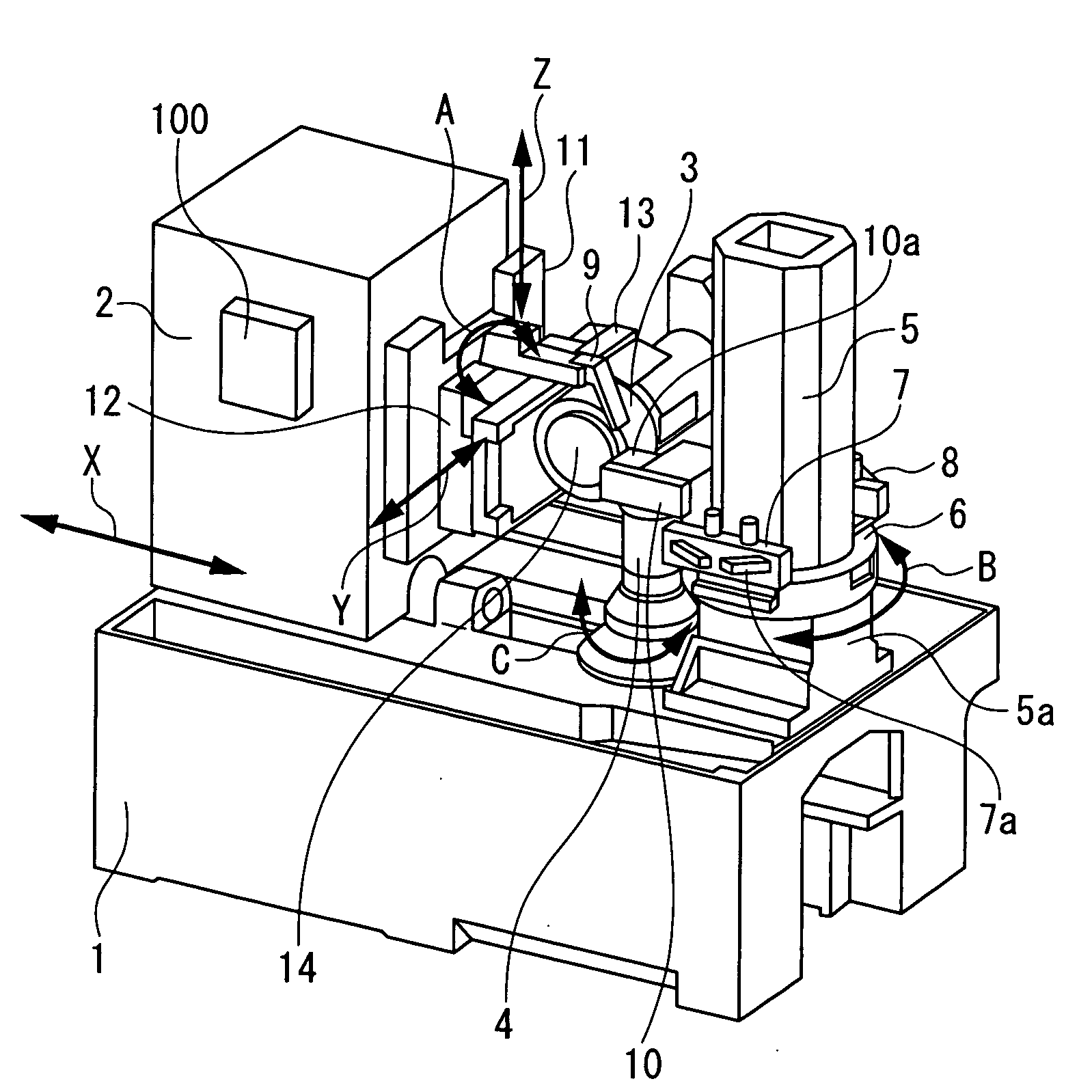
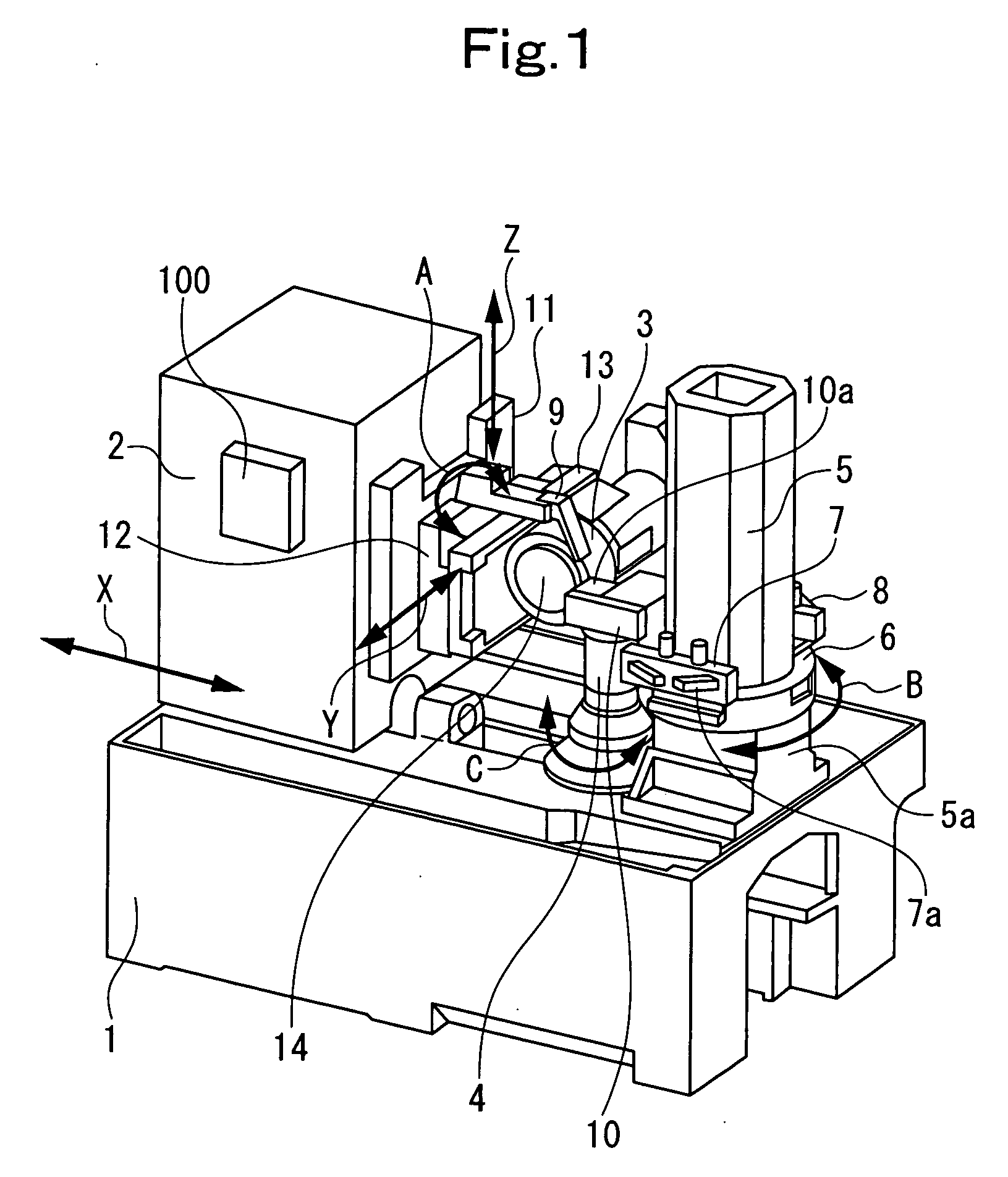
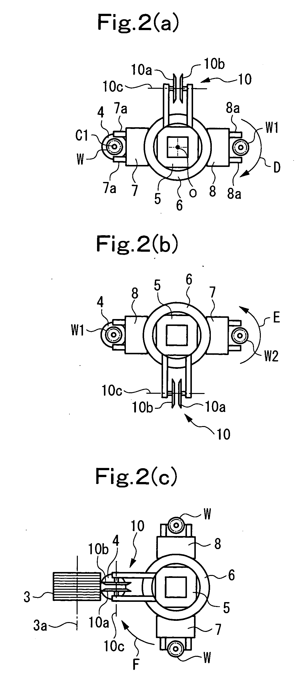
[0113]An embodiment of the present invention applied to the gear grinding machine shown in FIGS. 1 to 5(a), 5(b) will be described with reference to FIGS. 6(a) to 6(c).

[0114]According to this embodiment, the threaded grinding wheel 3 is dressed by the rotary dressing device 10, whereby the wheel pressure angle of the thread, which is formed spirally on the circumferential surface of the threaded grinding wheel 3, is progressively changed (gradually increased or gradually decreased) along a spiral path beginning at the starting point of the thread toward the end point of the thread.

[0115]In the present embodiment, the position of the rotary dressing device 10 is fixed, regardless of the progress of dressing, as shown in FIGS. 6(a), 6(b), and 6(c). Although the position of the rotary dressing device is fixed, the dressing tools 10a, 10b rotate in a vertical plane about the dresser axis 10c. The position of the threaded grinding wheel 3 is controlled by NC control using the NC device 2...


PUM

PropertyMeasurementUnit
distanceaaaaaaaaaa
pressure angleaaaaaaaaaa
rotational speedaaaaaaaaaa

Abstract

A gear grinding machine, a method for dressing a threaded grinding wheel, and a method for grinding a work are disclosed. A dressing tool is rotated in a vertical plane, with its position being fixed. The position of a threaded grinding wheel is NC-controlled, whereby the dressing tool is brought into contact with the starting point of the thread of the threaded grinding wheel at a somewhat lower surface of the circumferential surface of the threaded grinding wheel and, in accordance with the rotation of the threaded grinding wheel, the position of contact of the dressing tool with the threaded grinding wheel is moved along the circumferential surface of the threaded grinding wheel.

Description

BACKGROUND OF THE INVENTION[0001]1. Field of the Invention[0002]This invention relates to a gear grinding machine equipped with a threaded grinding wheel for performing grinding, and a rotary dressing device for dressing the threaded grinding wheel, a method for dressing a threaded grinding wheel, and a method for grinding a work.[0003]That is, the present invention is arranged to control the position of the threaded grinding wheel optimally by a numerical control (hereinafter referred to as NC control) function provided in the gear grinding machine so that the wheel pressure angle of the threaded grinding wheel can be easily dressing-modified, and the work can be ground by the dressing-modified threaded grinding wheel.[0004]In further detail, the present invention performs the following processing by effectively using an NC control function provided inherently in a gear grinding machine equipped with a rotary dressing device: That is, the present invention easily carries out dressi...

Claims


Application Information

Patent Timeline
Patent Type & Authority Applications(United States)
IPC IPC(8): B24B51/00B23F5/04B24B53/085
CPCB23F23/1225Y10S451/90B23F1/02B23F5/02
Inventor YANASE, YOSHIKOTOKATSUMA, TOSHIFUMI
Owner MITSUBISHI HEAVY IND MACHINE TOOL CO LTD
Why Eureka
Try Eureka